How fluid dynamics research helps predict pump cavitation




A pump can meet its rated flow and still experience cavitation when suction conditions change. Fluid dynamics research helps predict that risk by connecting the pressure available at the pump inlet with the local pressure drops and unsteady flow inside the impeller. The strongest assessment combines suction-system calculations, pump performance data, simulation, and measurements taken under representative operating conditions.
These methods answer different questions. Net positive suction head (NPSH) indicates how much suction pressure is available relative to the liquid’s vapor pressure. Computational fluid dynamics (CFD) can show where low-pressure regions and vapor structures may develop. Testing establishes how the physical pump responds. None of them, used alone, describes every consequence of cavitation.
Where cavitation starts and why location matters
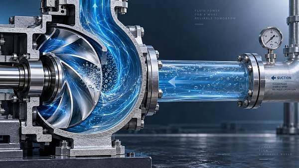
Cavitation occurs when local pressure in a flowing liquid falls sufficiently close to its vapor pressure for vapor-filled cavities to form. As those cavities move into regions of higher pressure, they collapse. Repeated collapse near a solid surface can create localized loading that contributes to pitting and material loss. Cavitation can also produce noise, vibration, fluctuating forces, and changes in pump performance.
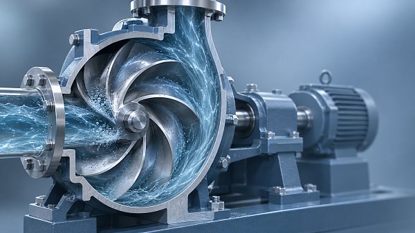
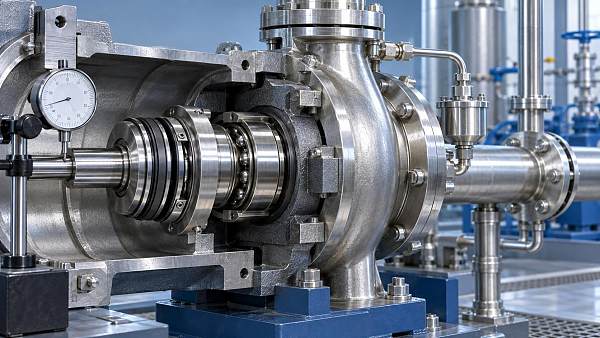
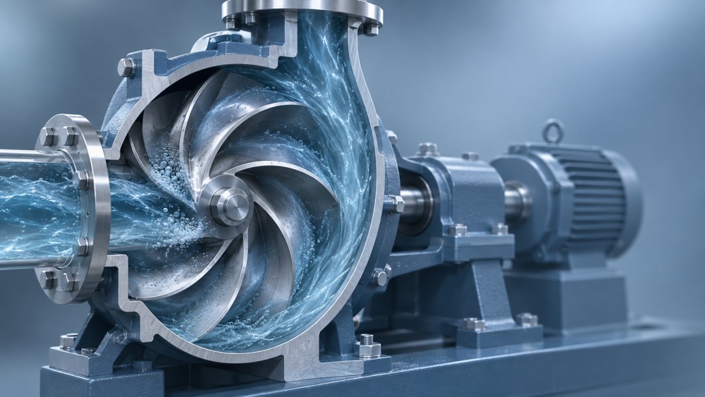
In a centrifugal pump, the impeller inlet is a common area of concern. Liquid accelerates as it enters the blade passages, and pressure can fall locally below the pressure measured at the suction flange. The lowest pressure may occur near a blade leading edge, within a tip-leakage flow, or in a region affected by recirculation. Its location depends on impeller geometry and operating point.
That distinction matters when interpreting measurements. A suction pressure gauge reports conditions at a particular location; it does not reveal the minimum pressure at every point inside the pump. Equally, a simulation showing a low-pressure spot does not by itself establish how quickly an impeller will erode. Damage depends on where cavities collapse, their dynamics, the material, and the duration and frequency of exposure.
Start with NPSH, but understand what it represents
NPSH expresses suction pressure relative to vapor pressure as a height of liquid. NPSH available (NPSHa) is a property of the system at a specified operating condition. NPSH required (NPSHr) is a pump performance characteristic supplied or established for a defined test criterion and operating point.
For a suction system, NPSHa is commonly evaluated from the absolute pressure at the liquid surface, the elevation difference between that surface and the pump reference elevation, suction-line losses, and the liquid’s vapor pressure at operating temperature. Pressure and velocity at the relevant measurement plane also matter when NPSHa is determined from readings at the pump inlet. The calculation must use consistent units and reference elevations.
Several conditions can reduce available suction head during operation:
- A falling source-tank level, which reduces the static head available to the pump.
- Higher liquid temperature, which generally raises vapor pressure.
- Increasing flow, which typically increases friction losses in the suction line.
- A fouled strainer, partially closed suction valve, or restrictive piping component, which adds pressure loss.
- Lower absolute pressure above the source liquid, such as in a vessel operating under vacuum.
A frequent mistake is to compare NPSHa and NPSHr only at the normal design point. A pump that has adequate margin at moderate flow may have less margin at a higher flow because system losses rise and the pump’s NPSHr can also change. Low-flow operation presents a different problem: internal recirculation and unstable inlet flow can produce cavitation even when the nominal NPSH comparison appears comfortable.
The NPSHr value also needs context. Pump data often uses a head-drop criterion, commonly expressed as NPSH3, at which total head has fallen by a specified amount during a suction performance test. Vapor formation and localized effects can begin before that point. Therefore, NPSHa exceeding an NPSH3 value is not proof that the pump is cavitation-free or protected against erosion.
Instead of treating a single margin as universally sufficient, assess the required margin against the pump design, liquid, operating range, reliability expectations, and applicable purchaser and supplier requirements. A continuous-duty pump handling hot liquid with limited maintenance access may justify a different approach from an intermittently operated water pump.
What fluid dynamics research adds to an NPSH calculation
NPSH is a useful screening parameter, but it compresses a complex flow field into a single value. Research into pump flow helps explain how the inlet geometry and internal flow turn a given suction condition into local cavitation risk.
CFD models divide the flow domain into many small regions and solve equations describing fluid motion. A pump model may include the suction piping, casing, impeller, and downstream passages, depending on the question being investigated. The resulting pressure and velocity fields can identify regions where liquid accelerates, separates from a surface, or circulates back toward the inlet.
For cavitation studies, a multiphase model can estimate the development of vapor within the liquid. Engineers can compare predicted vapor distribution across operating points, inlet pressures, or alternative impeller designs. A transient simulation can also examine how a vapor region changes as blades rotate and interact with surrounding flow.
This is especially useful when two designs have similar published NPSHr values but different flow patterns. One may show a concentrated low-pressure region near a vulnerable blade surface; another may distribute the flow differently. The comparison can guide design changes or identify where to place measurement instruments. It cannot, without further evidence, establish the service life of either impeller.
Read the model assumptions before the color plot
A convincing pressure contour is not the same as a validated prediction. The result depends on the geometry represented, the numerical mesh, the turbulence and cavitation models, and the imposed boundary conditions. Inlet pressure alone is not enough if the real pump receives a distorted or swirling flow that the model assumes to be uniform.
When reviewing a CFD study, ask whether it addresses the actual decision. A steady, non-cavitating calculation may be adequate for comparing broad pressure trends, but it cannot directly resolve the full behavior of collapsing vapor structures. A transient cavitation model can represent more of that behavior, but it also requires greater computational effort and remains sensitive to modeling choices.
Useful evidence includes a mesh-sensitivity assessment, a description of inlet and outlet conditions, the liquid properties used, and a comparison with test data at relevant operating points. The report should distinguish predicted vapor location from validated conclusions about head loss, vibration, or erosion. A model calibrated only at the best-efficiency point offers limited confidence in predictions far from that point.
Test conditions can change the conclusion
A controlled suction test helps establish how pump head changes as suction pressure is reduced at a given flow. Repeating the test at several flows produces a more useful picture than a single rating-point result. Additional measurements, such as vibration, acoustic response, pressure fluctuations, or visual observations where practicable, can reveal behavior that a head curve alone does not capture.
Each measurement has limits. Noise and vibration can indicate cavitation, but bearing faults, recirculation, air ingress, and other hydraulic disturbances can produce similar symptoms. A diagnosis is stronger when changes in the signal correspond with changes in suction pressure, temperature, tank level, or flow.
Test liquid and field liquid can also behave differently. Temperature, dissolved or entrained gas, viscosity, and other liquid properties may affect flow and cavitation behavior. A test result is most useful when its conditions are clearly documented and its relevance to the intended service is understood.
Air ingress deserves particular attention because it can resemble cavitation in operation. A leaking suction connection or a vortex at a poorly submerged intake can introduce gas even when the calculated NPSHa appears adequate. Gas entrainment and vapor cavitation can coexist, so the investigation should examine the suction source and piping as well as the pump.
Evaluate the pump and suction system together
Consider a centrifugal pump drawing warm liquid from a vessel whose level varies. At the expected operating point, the NPSH calculation may show a comfortable difference between available and required values. At low vessel level, higher temperature, and increased flow, that difference can narrow as static head falls, vapor pressure rises, and suction losses increase.
A useful assessment would calculate those combined conditions rather than changing each variable in isolation. It would then compare the resulting suction conditions with the pump’s performance across the relevant flow range. If CFD is available, the reviewer can examine whether predicted low-pressure regions shift or grow under those conditions. Field or test measurements can then help determine whether the predicted behavior has an observable operational consequence.
The corrective action depends on the cause. Raising liquid level, reducing suction-line restriction, lowering liquid temperature, or increasing vessel pressure may improve NPSHa where the process permits. Reducing pump speed can change both the system operating point and the pump’s suction requirements. A different impeller or pump arrangement may also be appropriate. Each option should be checked against the full duty: a change that improves suction conditions may affect flow, head, control range, or energy consumption.
Do not assume that increasing suction-pipe diameter alone resolves every problem. The layout may also contain elbows close to the inlet, uneven flow distribution, high points that collect gas, or intake arrangements that promote vortices. Conversely, replacing the pump will not necessarily solve a restriction or air leak upstream.
What to request in a technical assessment
The most useful deliverable is a traceable connection between operating conditions, prediction, and evidence. A practical review should establish:
- The operating envelope: flow range, speed, liquid composition and temperature, source pressure, and minimum and maximum liquid levels, including startup and upset conditions.
- The suction calculation: the reference elevation, pressure basis, vapor-pressure input, and losses from the source to the pump inlet, including allowances for normal fouling or changing valve positions.
- The pump data: head and NPSHr curves over the intended range, the criterion used to define NPSHr, and the test conditions behind the supplied values.
- The simulation scope: modeled geometry, boundary conditions, assumptions, sensitivity checks, and comparison with measurements.
- The operational evidence: trends in flow, suction pressure, temperature, vibration, noise, and inspection findings, aligned by time and operating state.
For a new installation, this information supports selection before equipment is committed. For an existing pump, it helps separate a persistent design limitation from a change in operation, fouling, or instrumentation. If available evidence conflicts, investigate the operating conditions and measurement locations before attributing the difference to a single cause.
The decision is not simply whether a model predicts vapor or whether NPSHa exceeds a catalog value. It is whether the pump and suction system can operate across the required envelope with an acceptable, documented risk of performance loss and damage. That assessment is most defensible when calculations, simulation, testing, and operating observations reinforce one another.
Facing technical bottlenecks in manufacturing or looking for more efficient industrial solutions? Leave your details below and let the engineering experts at FCSM solve them for you.
Related News
 How fluid dynamics research helps predict pump cavitationFluid Dynamics ScientistDiscover how fluid dynamics research combines NPSH, CFD and testing to predict pump cavitation risks and support more reliable pump operation.
 Which industrial pump technology suits corrosive wastewater?Fluid Dynamics ScientistExplore industrial pump technology for wastewater: compare centrifugal, AODD, and peristaltic pumps to find the right fit for corrosive fluids, abrasive solids, and reliable containment.
 Unibloc Adds CIP to QuickStrip PD200 Pumps in CleanPlus LineFluid Dynamics ScientistUnibloc QuickStrip PD200 pumps join the CleanPlus line with CIP capability. Explore how the redesign could streamline cleaning in food, beverage and chemical processing.
 How to size skid-mounted industrial pump sets for chemical transferFluid Dynamics ScientistSize industrial pump sets skid mounted for chemical transfer with confidence. Learn to verify flow, head, NPSH and motor power to avoid oversizing and improve reliability.
 Which pump impeller balancing methods prevent vibration at operating speed?Fluid Dynamics ScientistPump impeller balancing methods explained: compare static, single-plane, and two-plane balancing to reduce vibration, protect seals, and improve pump reliability.
 How fluid machinery selection affects energy use in chemical plantsFluid Dynamics ScientistFluid machinery selection shapes energy use in chemical plants. Learn how smarter pumps, compressors, valves, and drives reduce losses, improve control, and cut operating costs.
 How fluid dynamics analysis helps size a chemical process pumpFluid Dynamics ScientistFluid dynamics analysis helps engineers size chemical process pumps for reliable flow, NPSH margin, efficiency, and safer long-term operation.
 How fluid dynamic cavitation analysis predicts pump erosion riskFluid Dynamics ScientistFluid dynamic cavitation analysis reveals pump erosion risks before costly damage occurs. Learn how CFD pinpoints vapor collapse zones, off-design threats, and effective mitigation.
 How to identify industrial pump parts causing repeated seal failuresFluid Dynamics ScientistIndustrial pump parts can reveal why seals fail repeatedly. Learn how to inspect sleeves, bearings, shafts, flush lines, and hydraulic conditions for lasting repairs.
 How to size plunger pumps for high pressure dosing accuratelyFluid Dynamics ScientistPlunger pumps for high pressure dosing: learn how to size flow, pressure, suction, pulsation control, and materials for accurate, reliable chemical injection.
 What drives centrifugal pump price differences for similar duty points?Fluid Dynamics ScientistCentrifugal pump price differences explained: compare efficiency, materials, seals, testing, and lifecycle costs to choose the right pump package.
 What Should EPC Buyers Check in Fluid Equipment Technical Specs?Fluid Dynamics ScientistWhat should an EPC buyer check in fluid equipment technical specs? Explore key checks for duty range, materials, efficiency, interfaces, compliance, and lifecycle reliability.