How process control innovation in refineries reduces unplanned shutdowns




Unplanned refinery shutdowns rarely begin with a single dramatic failure. More often, a small control deviation develops into unstable flow, rising equipment load, off-spec conditions, a protective trip, or a maintenance intervention that cannot wait. Process control innovation reduces these events by making weak signals visible earlier and by giving the control system a more accurate, faster response to changing process conditions.
The practical objective is not to remove every disturbance. Feed composition changes, fouling, ambient temperature, utility variation, and equipment wear are normal realities. The objective is to prevent those disturbances from propagating across units faster than the process can absorb them. That requires reliable measurements, correctly sized final control elements, sound control logic, and a maintenance workflow that distinguishes a developing fault from ordinary operating noise.
Where shutdown chains usually start
A refinery unit is a connected pressure, temperature, flow, and composition system. A restriction in one location can alter conditions well beyond its immediate piping run. For example, a control valve with increasing stiction may hold a flow loop near its setpoint for long periods, then release suddenly. The resulting flow step can upset furnace firing, column pressure, reflux balance, downstream level control, or pump suction conditions. A local valve problem therefore becomes a unit stability problem.
Similar escalation occurs when measurements drift without appearing failed. A biased temperature transmitter may cause excess heat input. A plugged impulse line can slow pressure feedback. A level instrument exposed to coating or foam can report a falsely stable vessel inventory until the actual level reaches a constraint. Traditional alarm systems often identify the final consequence, such as high pressure or low suction level, rather than the earlier source of instability.
Process control innovation in refineries focuses on the period between the first abnormal signature and the protective limit. It combines better field diagnostics with contextual analysis: whether a valve command and valve travel agree, whether a pump is approaching hydraulic instability, whether a pressure oscillation follows a feed change, and whether multiple alarms reflect one initiating condition rather than several independent problems.
Make control valves observable instead of treating them as passive hardware
Control valves are frequently the final element that determines whether a controller can actually correct a disturbance. A loop may have sophisticated tuning, but it cannot regulate tightly if the valve has excessive friction, dead band, air leakage, inadequate actuator thrust, or an installed flow characteristic that differs sharply from the design assumption.
Smart positioners provide useful diagnostic information when it is interpreted against service conditions. Command-versus-travel deviation, repeated hunting, elevated breakaway pressure, slow stroking, and abnormal air consumption can indicate developing mechanical or pneumatic problems. None of these signals should be judged in isolation. A slow response could originate from a sticky stem, but it could also result from a restrictive air supply, undersized tubing, a clogged air filter, cold ambient conditions, or a controller output deliberately rate-limited to protect the process.
Valve travel trends are especially valuable near common operating positions. A valve that spends most of its time nearly closed may be oversized, making small controller movements produce disproportionate flow changes. A valve that operates close to full travel may have insufficient capacity, excessive pressure loss elsewhere in the line, or a changed process duty. Both conditions reduce control authority and make disturbances harder to contain. Replacing the positioner without examining pressure drop, fluid properties, cavitation risk, and actual required flow can leave the root problem untouched.
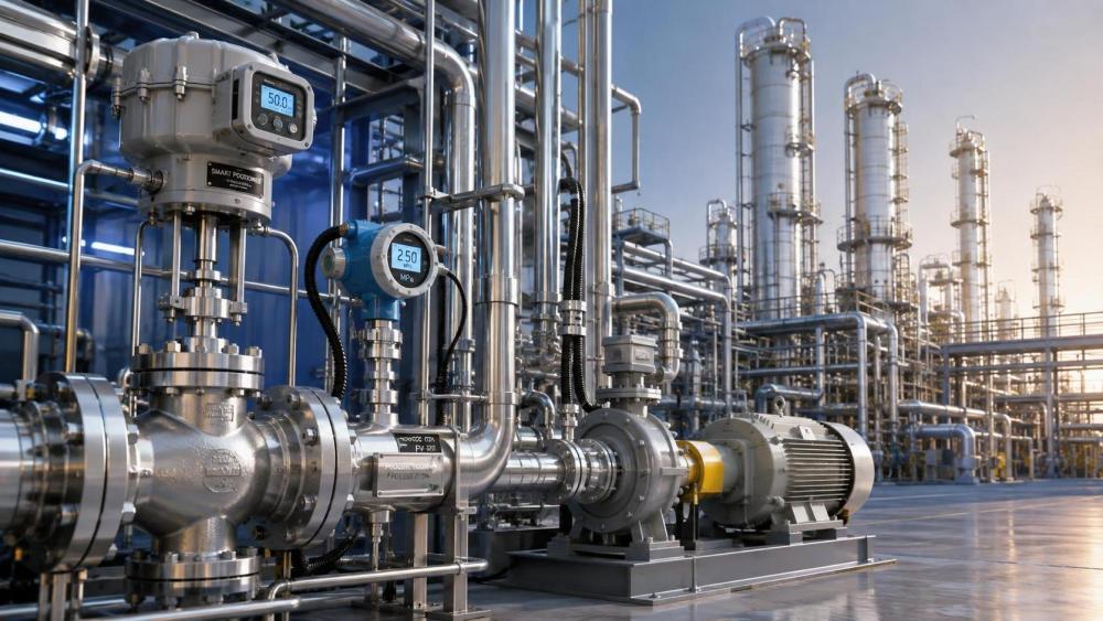
For flashing or cavitating liquid service, trim selection and installation details affect availability as much as software does. High velocity through a restrictive trim can produce vibration, noise, trim erosion, and downstream pipe damage. A pressure-control loop might appear unstable because the valve characteristic is changing as erosion progresses. In severe service, multi-stage pressure reduction, hardened trim materials, appropriate body geometry, and an accurate review of differential pressure across the valve may be needed before tuning changes will hold.
Use real-time data to separate disturbance from equipment degradation
Refinery control rooms already handle large volumes of data. The improvement comes from correlating measurements that describe the same physical event. A rising discharge pressure alone can have many explanations. Rising discharge pressure together with falling flow, increasing pump vibration, reduced suction margin, and a change in motor load points to a much narrower set of possibilities.
Integrated fluid-system monitoring should connect process measurements with equipment-condition indicators where the connection is technically meaningful. On a centrifugal pump circuit, relevant signals may include suction and discharge pressure, flow, bearing condition, seal system status, motor current, valve position, and minimum-flow recycle activity. The interpretation changes with operating mode. A low-flow condition during startup is expected in a different way than a low-flow condition while a unit is at steady throughput.
Pressure and flow should also be read together. A falling flow rate may reflect a closing downstream valve, a plugging exchanger, reduced pump performance, density change, instrument error, or an upstream supply constraint. The differential pressure across a strainer or exchanger, the control-valve position, and the pump speed often clarify which explanation fits. Treating a single trend as proof can trigger unnecessary field work or conceal a real restriction behind an apparently plausible instrument diagnosis.
Patterns that deserve earlier intervention
- A control output that repeatedly cycles while the measured variable has a growing lag can signal valve friction, process dead time, or an aggressive tuning setting. The corrective action differs for each cause.
- Frequent opening of a recycle valve may protect a pump from low flow, yet it can also reveal that the main process demand is fluctuating, a downstream restriction is developing, or the pump has been selected with excessive head margin.
- A stable average temperature can conceal short oscillations that stress furnace tubes, reactor temperature limits, or separation performance. Trend resolution must be sufficient to expose the cycle rather than smoothing it away.
- Several alarms arriving within seconds are often one propagating event. Sequence-of-events records are more useful than alarm counts when identifying the first deviation.
Predictive analytics must be tied to process physics
Predictive methods are most effective when they test a clear operational hypothesis. A model can compare expected pump head against measured pressure and flow, flagging a departure that warrants review. It can detect that a valve needs progressively greater actuator pressure to achieve similar travel. It can identify a heat exchanger whose temperature approach and pressure drop are drifting together in a pattern consistent with fouling.
These functions become unreliable when the data set mixes incompatible operating states. Startup, feed transitions, regeneration periods, equipment recirculation, and maintenance bypass arrangements should not be treated as normal steady-state data. A model trained on mixed conditions may label valid transitions as faults, or worse, normalize the early stages of an actual problem. State-based analysis is therefore important: define the operating modes first, then compare equipment behavior within the applicable mode.
Prediction also needs a decision path. An alert without an associated engineering review can become another ignored notification. A useful event includes the affected loop or equipment item, the observed deviation, supporting process variables, the duration, the relevant operating state, and the consequence if the trend continues. That information allows a review to determine whether the next action is a calibration check, valve signature test, inspection during the next controlled opportunity, temporary operating constraint, or immediate protective response.
Control strategy changes that reduce propagation
Many shutdowns are preceded by loop interaction rather than a failed instrument. A pressure controller and a flow controller can fight over the same valve. A level loop tuned for rapid correction can disturb a downstream fractionation section. A furnace outlet temperature controller may overreact to a noisy measurement and drive fuel demand into repeated swings. Modern control improvements address these interactions through hierarchy, constraint handling, filtering selected for the process time scale, and clearer ownership of final elements.
Feedforward control is useful where a measurable disturbance arrives before its effect. A change in feed flow can inform a furnace fuel adjustment before outlet temperature has moved substantially. The feedforward signal must be validated, scaled correctly, and paired with feedback correction. If the upstream flow measurement is unreliable or the feed heating value changes independently of flow, feedforward alone can introduce a new error.
Override and constraint control can protect equipment before emergency trips are reached. A pump minimum-flow controller, for instance, can take priority over production flow demand when hydraulic stability is threatened. The design must make the priority visible and testable. Hidden overrides cause confusion during troubleshooting because the primary controller appears ineffective while another logic layer is controlling the valve.
Advanced control applications should be introduced only after the underlying regulatory loops and field devices are dependable. Optimizers cannot compensate for a drifting analyzer, a mischaracterized valve, or pressure transmitters that do not share a consistent reference. Starting with unstable basic control often produces a complex system that is difficult to trust during an upset.
Design the implementation around shutdown-critical scenarios
A focused implementation begins by mapping credible pathways from small deviations to unit curtailment or trip. The map should include initiating measurements, manipulated elements, process constraints, protective actions, bypasses, and the time available before consequences become severe. This is more useful than applying identical monitoring depth to every loop.
Consider a distillation pressure-control problem. The immediate symptom may be high column pressure, but the initiating mechanism could be condenser performance loss, non-condensable accumulation, reflux disruption, compressor limitation, or a pressure-control valve that is no longer following its demand. Each mechanism leaves a different fingerprint across condenser temperatures, cooling-medium conditions, reflux flow, valve travel, compressor load, and vent behavior. The monitoring design should preserve those distinctions.
Installation quality remains part of process control performance. Impulse lines need proper routing and protection from plugging or inappropriate heat effects. Differential-pressure taps require the right orientation for the service. Analyzer sample systems need stable pressure, representative sample conditioning, and maintainable filtration. Valve actuators require clean, dry instrument air at the pressure assumed in sizing. A digital diagnostic layer cannot correct errors created by poor field installation.
Turn diagnostics into maintainable work
Condition alerts reduce shutdown risk only when they are connected to a controlled response. A valve showing early stiction may remain suitable for service until a planned maintenance window, while a valve in an emergency isolation duty requires a different escalation threshold. Criticality should reflect the consequence of losing function, available redundancy, bypass configuration, process inventory, and the ability to place the unit in a stable reduced-rate condition.
Maintenance records should capture the as-found condition, not merely the replaced component. Stem condition, packing wear, trim damage, actuator diaphragm integrity, instrument-air contamination, calibration offset, and installed orientation provide feedback to engineering. Over time, this separates random failures from recurring design or service mismatches. Repeated replacement of the same component without documenting the mechanism is expensive and does little to prevent the next shutdown.
During commissioning and modifications, loop tests need to verify the complete control path: sensor response, signal conditioning, controller action, output limits, valve direction, fail position, interlock interaction, and response under representative pressure conditions. A bench stroke test confirms movement; it does not confirm installed control performance. Testing only at ambient or without process differential pressure can miss actuator force limitations, trim instability, or leakage that emerges in service.
The strongest shutdown-reduction programs treat control performance as an operating asset with a lifecycle, not as a one-time automation project. When field behavior, process context, and maintenance evidence are reviewed together, unstable conditions become identifiable while there is still time to correct them under control rather than after a trip has dictated the schedule.
Related News
 What drives industrial wastewater treatment cost per cubic meter?Dr. Alistair VaughnIndustrial wastewater treatment cost per cubic meter depends on influent load, effluent targets, energy, technology, and sludge disposal. Explore the key cost drivers.
 How to verify CE compliance for fluid separation equipmentDr. Alistair VaughnFluid separation equipment CE verification made practical: learn how to check declarations, risk assessments, technical files, pressure safety, and installation readiness.
 Separation equipment trends reshaping industrial wastewater treatmentDr. Alistair VaughnSeparation equipment trends are reshaping industrial wastewater treatment through smarter membranes, modular systems, digital monitoring, and resource recovery strategies.
 When stainless steel separation equipment is the right choice for hygienic processesDr. Alistair VaughnStainless steel separation equipment: discover when hygienic design, corrosion resistance, CIP cleanability, and lifecycle reliability make it the smart choice.
 What to assess before choosing a process industry automation supplierDr. Alistair VaughnChoose a process industry automation supplier with confidence. Assess engineering depth, lifecycle reliability, digital integration, energy performance, and safety before you buy.
 How process control innovation in refineries reduces unplanned shutdownsDr. Alistair VaughnDiscover how process control innovation in refineries detects early deviations, improves valve and equipment reliability, and helps prevent costly unplanned shutdowns.
 What should a zero liquid discharge systems integrator include in its proposal?Dr. Alistair VaughnZero liquid discharge systems integrator proposal checklist: compare guarantees, utilities, scope, controls, waste handling, and lifecycle risk before award.
 Industrial wastewater treatment plant design: sizing for flow and loadDr. Alistair VaughnIndustrial wastewater treatment plant design guide: size systems for peak flow, pollutant loads, reliability, compliance, and lower lifecycle costs.
 Can predictive maintenance and machinery diagnostics prevent downtime?Dr. Alistair VaughnPredictive maintenance machinery diagnostics help reduce unplanned downtime by detecting early equipment issues, improving reliability, and enabling smarter maintenance decisions.
 Can a digital transformation machinery platform cut unplanned downtime?Dr. Alistair VaughnDiscover how a digital transformation machinery platform connects asset data, maintenance workflows, and process insights to reduce unplanned downtime.
 How water treatment equipment sizing affects operating costsDr. Alistair VaughnWater treatment equipment sizing shapes energy, chemical, and maintenance costs. Learn how to balance flow, pressure, recovery, and reliability for efficient operation.
 When does food processing automation justify the upfront investment?Dr. Alistair VaughnIndustrial automation solutions for food processing: discover when automation delivers measurable ROI through higher throughput, lower waste, reliable utilities, and stronger food safety control.