How to detect leaks in industrial compressed air systems




A production line is complaining about low air pressure, but the compressor appears to be running normally. Before replacing a component or raising the pressure setpoint, consider what may be escaping between the compressor room and the point of use. A small leak at a quick coupling, a damaged hose or an inaccessible valve can leave technicians chasing symptoms rather than the cause.
For after-sales maintenance teams, the challenge is not simply finding a hiss. It is separating real leakage from normal air consumption, locating the fault safely and proving that the repair worked. This guide explains compressed air system leak detection methods for industrial maintenance, including ultrasonic surveys, leak-detection fluids and pressure-based checks.
Start with the system, not the suspected component
Ask the operator when the problem occurs. Is pressure falling only when several machines start together, or does the compressor continue to cycle during a quiet period? A localized pressure drop may point to a restriction, an undersized hose or a heavily loaded branch rather than a leak. On the other hand, a compressor that repeatedly loads when production is stopped warrants a closer look at unintended air consumption.
Before testing, review the site’s air system layout and identify compressor controls, receivers, isolation valves, dryers and critical users. Record the operating pressure and the conditions under which the complaint occurs. If the system serves instruments, safety devices or essential production equipment, agree on test boundaries and isolation plans with the site operator.
Do not assume that every airflow during an idle period is leakage. Automatic drains, air-operated controls, air bearings and other equipment may have legitimate demand. Conversely, a machine that appears idle may contain cylinders or valves that remain pressurized and leaking internally.
Where to look for compressed air leaks
Begin at accessible points that experience movement, vibration or frequent connection and disconnection. Then work systematically along each branch rather than jumping between obvious noises.
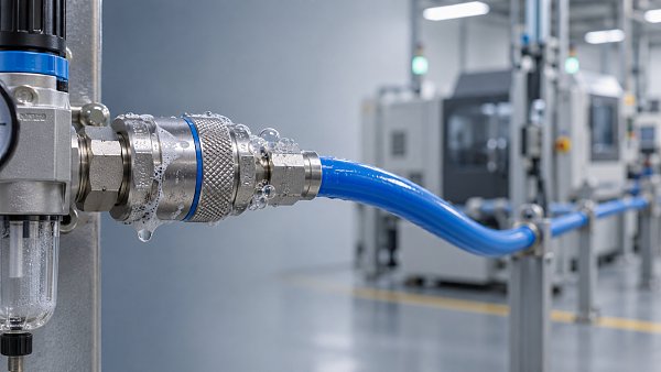
- Hoses and quick-connect couplings: Check for abrasion, loose connections, damaged seals and leaks that appear only when a hose is moved.
- Threaded joints and fittings: Inspect connections around regulators, filters, lubricators, manifolds and pressure gauges.
- Pneumatic valves and cylinders: Listen at exhaust ports and inspect actuators for leakage associated with a particular machine state.
- Condensate drains: Check whether a drain is passing air continuously or operating as designed.
- Pipework and isolation valves: Look for damaged pipe sections, leaking joints and valves that do not seal when closed.
- Point-of-use equipment: Inspect blow guns, nozzles, flexible drops and connections inside machine guarding, subject to site access procedures.
A component can leak only under certain conditions. A solenoid valve may seem sound until it changes state; a hose may leak when the machine moves. Record the operating state during each check so the result can be reproduced.
Choose a detection method that fits the job
No single technique answers every maintenance question. Ultrasonic instruments are often the fastest way to locate leaks across a running plant, while a liquid test can pinpoint a suspect joint. Pressure and flow measurements are useful for assessing a section or the wider system, but they do not usually identify the exact opening on their own.
Ultrasonic leak detectors: useful in noisy production areas
Air escaping through a restriction generates ultrasonic sound that is above the range of normal hearing. A suitable detector converts that signal into an indication a technician can hear or see. This makes it possible to survey equipment even where ordinary listening is overwhelmed by machinery.
Start with the instrument settings and accessories recommended by the manufacturer. Scan from a practical distance, then move closer and reduce sensitivity as needed to narrow the source. Where safe access permits, a focusing attachment or contact probe may help distinguish a leak from nearby sources. Follow the signal around the fitting or component rather than assuming the first strong reading identifies the exact point.
Keep in mind that pneumatic exhausts, electrical equipment, friction and other ultrasonic sources can produce misleading signals. Confirm suspected leaks with an appropriate second check, such as leak-detection fluid on an accessible external joint, and compare readings before and after repair. Avoid touching moving or energized equipment with an instrument or accessory.
Some detectors estimate leak rate or assign a cost. Treat those figures as screening estimates unless the instrument’s method, distance, pressure and site conditions support a more reliable assessment. A decibel reading alone is not a direct measurement of airflow.
Leak-detection fluid: simple confirmation at the joint
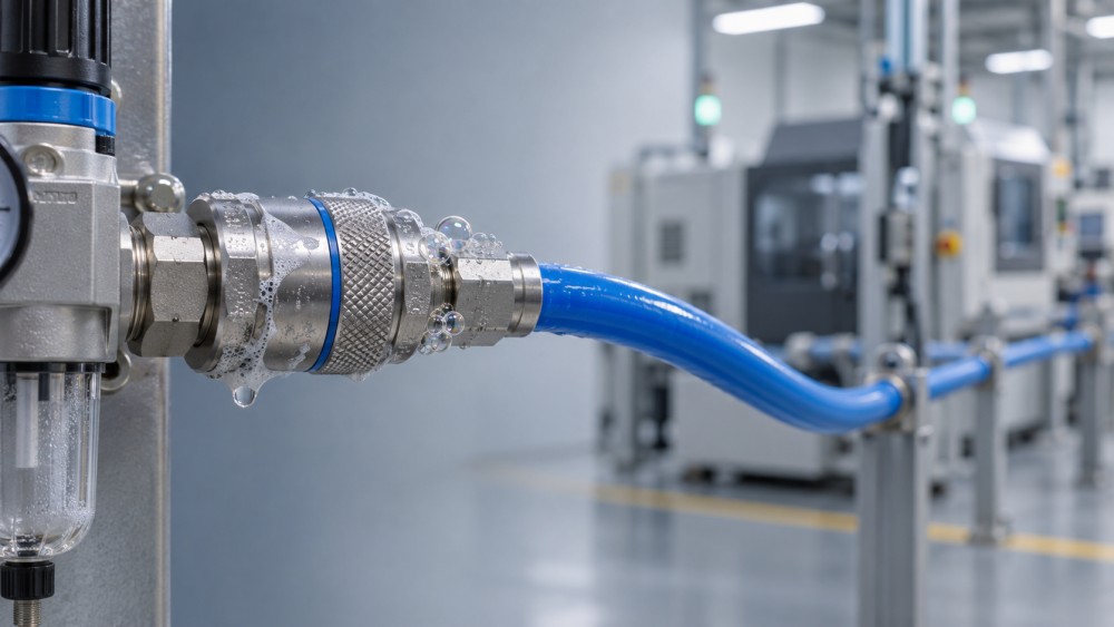
A compatible commercial leak-detection solution, or another site-approved solution, is valuable when the suspected area can be reached safely. Apply it to the joint while the line is pressurized and watch for bubbles that grow continuously. A one-time cluster of bubbles caused by application is not necessarily a leak.
This method works well on fittings, hose ends and valve bodies. It is less practical for long overhead networks or components hidden behind guards. Do not spray electrical devices, hot surfaces or sensitive equipment. Check material compatibility, follow the solution manufacturer’s instructions and clean off residue where required by site procedures.
Never use a flame to search for a leak, and never use your hand to probe for escaping high-pressure air. Compressed air can cause serious injury.
Listening and visual checks: a useful starting point
In a quiet area, an audible hiss can lead directly to a damaged coupling or open connection. Visual inspection may reveal a split hose, a loose fitting or a drain discharging air. These checks require little equipment and can be effective during an initial walk-through.
The limitation is coverage. Background noise can hide leaks, and air escaping behind a guard or above a ceiling may not be visible. Use listening as a clue, not as proof that the rest of the network is sound.
Pressure decay and flow checks: assess a defined section
A pressure decay test can indicate whether a safely isolated section is losing air. With site approval, isolate the section, stabilize it at a known pressure and record pressure over a measured period. Include temperature and test conditions in the record: cooling air can lower pressure even when there is no leak. Gauge accuracy, trapped volumes, intentional users and internal leakage across isolation valves can also affect the result.
A pressure drop identifies a possible loss; it does not show where the leak is. Subdivide the network where practical, then use an ultrasonic detector or leak-detection fluid to locate the fault. Do not disconnect or dismantle a pressurized section simply because a gauge indicates a drop.
Where a suitably installed flow meter is available, measure flow into a defined section during a stable non-production period. Account for permitted continuous users and meter limitations. A compressor load/unload observation can provide a rough indication of off-hours demand, but it is influenced by controls, storage and legitimate consumption. It should not be presented as an exact leak measurement without a suitable method and supporting data.
A field workflow for finding and fixing the fault
- Establish the complaint. Record pressure readings, operating conditions, affected equipment and the time the problem occurs. Confirm whether the problem is plant-wide or limited to one branch.
- Plan a safe survey. Obtain authorization, review hazards and identify equipment that cannot be isolated. Arrange access equipment and site-required personal protective equipment.
- Survey in a consistent direction. Work from the compressor room through distribution branches to end users, or divide the site into marked zones. Check both production and idle states where relevant.
- Confirm and tag each finding. Record the location, component, test method, pressure and machine state. Add a photograph or site reference if it will help the repair technician return to the correct point.
- Repair under an approved isolation procedure. Depressurize, lock out and verify zero energy as required before opening a line or replacing a component. Include stored pressure in receivers, trapped sections and actuators in the assessment.
- Repressurize and verify. Restore the system according to site procedure, check the repaired point under representative conditions and record the result.
This workflow avoids a common service-call frustration: a leak is noted, but the repair team cannot find it later or cannot tell whether the machine was running when it occurred. A short, precise record is more useful than a long list of unqualified observations.
Which leaks should be repaired first?
Safety comes before estimated energy savings. Escaping air near personnel, damaged hoses, unstable fittings or faults affecting critical controls should be handled according to site risk procedures. A leak that disrupts a production machine may also deserve attention before a larger but less consequential leak elsewhere.
For the remaining findings, consider the likely air loss, operating hours, accessibility and repair effort. A leak present around the clock may be more significant than one that occurs briefly during a machine cycle. Grouping repairs by shutdown window or physical location can reduce repeat access work, particularly on overhead pipework.
If an instrument provides a leak-rate estimate, document how it was obtained. To estimate potential energy cost, the site also needs a defensible relationship between the air saved and the compressor system’s electrical consumption, along with operating hours and energy price. The saving is not automatic: compressor controls must be able to respond to reduced demand. Check with the site’s compressor specialist before turning an estimated leak rate into a financial claim.
Verify the repair—and check the wider system
Use the same detection method at the same location after the repair, at a comparable pressure and in the machine state that produced the original finding. For a joint confirmed with fluid, look for the absence of growing bubbles. For an ultrasonic finding, compare the signal while checking for nearby background sources. If a cylinder or valve leaked only during a particular part of its cycle, repeat that condition safely.
Where several leaks were repaired, compare off-hours flow, pressure behavior or compressor operation with the baseline. Keep the comparison conditions as close as possible: production demand, pressure setpoint, dryer operation and ambient temperature can all change the result. A quieter network does not necessarily mean the pressure problem is solved if a restriction or control issue remains.
Close the service record with the repaired components, verification method, operating conditions and any unresolved findings. If a leak returns, look beyond the seal itself. Repeated failures can point to hose movement, vibration, misalignment, contamination or a connection that is unsuitable for the application. A sound repair fixes the immediate escape; a useful after-sales report gives the site enough information to prevent the next call.
Facing technical bottlenecks in manufacturing or looking for more efficient industrial solutions? Leave your details below and let the engineering experts at FCSM solve them for you.
Related News
 Beijing Plan Calls for Higher Efficiency in Compressors, Pumps and Other EquipmentDr. Alistair VaughnBeijing's zero-carbon factory plan targets higher efficiency in compressors, pumps and other equipment. Explore what buyers and suppliers should verify.
 How does ISO 16889 measure hydraulic filter performance?Dr. Alistair VaughnIndustrial filtration and separation: discover how ISO 16889 measures hydraulic filter efficiency, beta ratios and contaminant capacity to help you compare filters with confidence.
 Sulzer and NABEP Agree to Support Rebuilding of Venezuelan Heavy-Oil UpgraderDr. Alistair VaughnSulzer and NABEP agree to support Venezuela’s Petrocedeño heavy-oil upgrader rebuild. Explore the supply-chain implications and key questions for suppliers.
 How to size control valves for boiler feedwaterDr. Alistair VaughnSize control valves for boiler feed with confidence. Learn to calculate Cv, assess low-load control, and prevent cavitation for reliable operation.
 How to detect leaks in industrial compressed air systemsDr. Alistair VaughnExplore compressed air system leak detection methods for industrial facilities. Find leaks safely, prioritize repairs, and verify results to reduce air loss.
 How to assess an industrial water treatment supplier's after-sales supportDr. Alistair VaughnAssess an industrial water treatment supplier’s after-sales support with practical checks for response times, technical expertise, spare parts and service costs.
 Selecting C20 Ductile Iron Pipe for Buried Water MainsDr. Alistair VaughnC20 ductile iron pipe selection starts with more than pressure class. Explore surge, soil, joint and approval checks to specify buried water mains with confidence.
 How industrial machinery retrofit trends are shaping energy efficiencyDr. Alistair VaughnExplore industrial machinery retrofit trends, from smart controls to system upgrades, and discover how to improve energy efficiency without compromising reliability.
 Gland Packing Market Forecast to Grow Through 2035 on Pump and Valve MaintenanceDr. Alistair VaughnGland packing market growth through 2035 is driven by pump and valve maintenance. Explore demand trends and opportunities in high-performance sealing.
 ComVac ASIA 2026 Opens in Shanghai, Focusing on Compressor IntelligenceDr. Alistair VaughnComVac ASIA 2026 opens in Shanghai, spotlighting intelligent compressors, digitalization and emerging opportunities in compressed air and vacuum technology.
 Industrial Compressor Overheating: Causes and Maintenance ChecksDr. Alistair VaughnIndustrial compressor selection starts with understanding overheating. Explore key causes, safety checks and maintenance tips to prevent recurring shutdowns.
 Industrial Compressor Sizing: Matching Capacity to DemandDr. Alistair VaughnMaster industrial compressor selection with practical guidance on sizing capacity, pressure, duty cycles and storage to meet demand efficiently.