How water treatment equipment sizing affects operating costs




Water treatment equipment sizing sets the operating cost profile long before a system is commissioned. A pump selected for the highest possible flow, a membrane rack sized only for nominal throughput, or a filter vessel chosen without regard to backwash demand can all create a plant that meets capacity on paper while consuming excessive power, chemicals, water, and maintenance labor in service.
The practical sizing target is the expected operating envelope: minimum, normal, high, and short-duration peak conditions; feedwater quality variation; seasonal temperature changes; cleaning and backwash cycles; redundancy requirements; and downstream pressure constraints. Peak flow remains relevant, but it should be treated as one condition within a duty profile rather than the sole design point.
Flow and pressure determine the energy burden
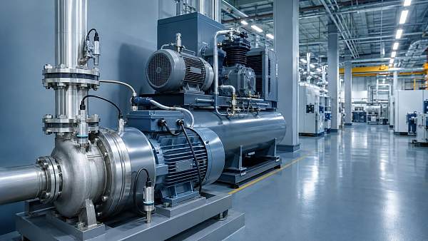
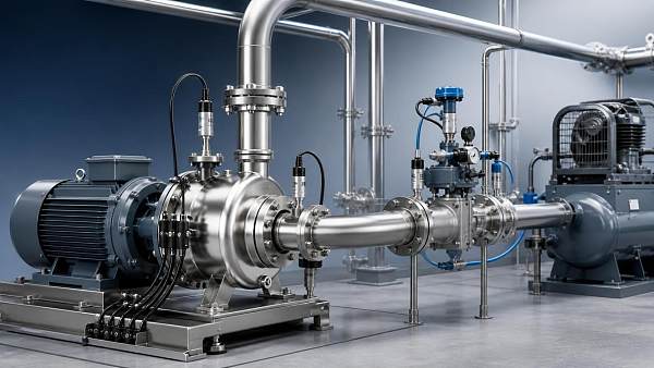
Pumping energy is often the most visible consequence of poor water treatment equipment sizing. The pump must overcome static lift, pipe friction, fittings, treatment equipment pressure loss, control valve losses, and the required pressure at the discharge point. When the specified duty point is too high, the selected pump may run far from its best efficiency region during most operating hours. Throttling then becomes a routine method of reducing flow, converting useful pressure into avoidable loss across a valve.
Oversized centrifugal pumps can also create unstable control at low demand. A control valve may operate close to its shutoff position, where a small position change causes a large flow change. This can lead to cycling, poor level control, vibration, elevated noise, and higher wear at valve trim and pump internals. Where flow varies materially, a properly selected variable-frequency drive may reduce energy use, but it cannot fully correct an impeller, motor, or hydraulic layout selected without a realistic flow profile.
Undersizing produces a different cost pattern. A pump that repeatedly operates near the end of its curve may not maintain required pressure after filters foul, membranes age, or inlet conditions deteriorate. The apparent savings in installed capacity can be lost through interrupted production, frequent cleaning, shortened mechanical seal life, or the need to install an additional booster pump after commissioning.
System curve development should therefore include clean and fouled conditions. Pressure drop through cartridge filters, multimedia beds, membrane elements, strainers, piping, and heat exchangers changes over time. A clean-system calculation alone can understate required head, while a design based entirely on maximum fouling can force normal operation into a wasteful throttled condition. The better approach is to define the acceptable pressure-drop range and verify that the pump and control arrangement remain controllable throughout it.
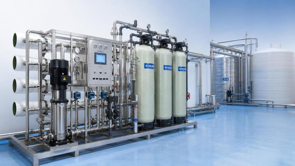
Membrane capacity affects both recovery and cleaning frequency
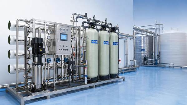
Reverse osmosis, nanofiltration, ultrafiltration, and microfiltration systems are particularly sensitive to sizing assumptions because hydraulic loading and water chemistry are closely linked. Membrane area should be selected against feedwater composition, temperature, target flux, recovery, concentrate constraints, and anticipated fouling tendency. Applying a high initial flux to reduce the number of elements or skids may lower first cost, yet it can increase transmembrane pressure, concentrate polarization, cleaning frequency, and replacement demand.
Feedwater temperature matters because viscosity changes with temperature. A system that appears to have surplus capacity during warm conditions may require substantially more pressure during cold operation. If the high-pressure pump is sized around warm-water performance, permeate production may fall below requirement in colder periods. Conversely, selecting for the coldest theoretical condition without considering how often it occurs can create excessive part-load energy use for the rest of the year.
Recovery must be evaluated with the same discipline. Higher recovery reduces concentrate volume, but it raises dissolved solids concentration on the feed side of the membrane. Depending on the water analysis, this can increase scaling risk, osmotic pressure, and antiscalant demand. The economical point is not automatically the highest attainable recovery. It is the recovery at which added permeate production does not impose disproportionate pumping, pretreatment, chemical, cleaning, or concentrate-management costs.
Membrane trains also need enough staging flexibility to accommodate maintenance without pushing the remaining vessels beyond their intended flux or pressure range. A simple duty/standby philosophy can be appropriate for some systems, but it should be examined together with feed variability and cleaning duration. During chemical cleaning, rinse and return-to-service steps require temporary flow paths, compatible valves, drainage capacity, and instrumentation that are often omitted from early sizing calculations.
Filters are sized by solids loading, not only hydraulic flow
Filter vessels and media beds are commonly selected using a nominal service rate. That rate is useful, but it does not predict run length by itself. Influent turbidity, particle size distribution, biological growth, coagulant carryover, oil contamination, and irregular upstream discharges determine how quickly differential pressure rises. A compact filter design with a high loading rate may require frequent backwashing, increase wastewater volume, and consume more air or water during cleaning.
For granular media filters, bed depth, media gradation, freeboard, underdrain design, and backwash expansion all affect lifecycle performance. Insufficient freeboard can permit media loss during backwash. A weak underdrain distribution pattern can leave zones that do not clean effectively, shortening filter runs even when the vessel diameter appears adequate. Backwash flow must also be available at the required temperature and pressure; a backwash pump selected only for average plant demand may fail to fluidize the bed properly.
Cartridge and bag filter housings require a separate evaluation. Their nominal flow ratings can be misleading when the differential pressure allowance is narrow or the feed contains deformable solids. Selecting too few elements raises velocity through each cartridge and causes rapid pressure increase. Selecting an excessively large housing may reduce replacement frequency but increases hold-up volume, installation weight, floor space, and the amount of liquid handled during element changeout. Housing material must be compatible with water chemistry and cleaning agents; stainless steel grade, lined carbon steel, fiberglass-reinforced plastic, and thermoplastic construction each carry different limits for chlorides, temperature, impact resistance, and connection design.
Control valve authority can eliminate hidden losses
Control valves are often sized after pump selection, even though the two decisions are inseparable. A valve with excessive capacity relative to the process flow has poor authority: it remains nearly closed during normal operation and provides limited useful control resolution. The resulting pressure loss may be high, while the actual regulating range is narrow.
Valve sizing should use the fluid density, viscosity, vapor pressure, operating pressure, normal and maximum flow, and available differential pressure. For high-pressure or flashing services, cavitation and noise must be considered alongside flow coefficient. A valve trim that is too restrictive can create local velocity and pressure conditions that damage trim surfaces or generate unstable flow. A trim with too much capacity can make flow control erratic. Characterized trim, appropriate actuator sizing, and a positioner with reliable feedback can improve stability only when the fundamental valve capacity is suitable.
Isolation valves, check valves, pressure-reducing valves, and relief devices should be reviewed as part of the hydraulic system rather than treated as independent catalogue items. An undersized check valve can add persistent head loss. A poorly located pressure-reducing valve can cause pressure fluctuations that affect membrane feed. A relief device that discharges frequently may indicate a control or thermal expansion issue rather than a component failure.
Design around actual operating modes
A sizing package should document more than a single process flow diagram. It should establish operating modes such as normal treatment, low-demand operation, peak demand, startup, shutdown, filter backwash, membrane flush, chemical cleaning, tank turnover, and loss of a duty pump. Each mode changes flow direction, pressure, valve position, and equipment availability.
Tank sizing deserves the same attention. Larger storage can dampen short-duration peaks and permit treatment equipment to run closer to a stable, efficient rate. However, excessive residence time may introduce water quality concerns in some applications, increase structural cost, and require more recirculation or disinfection control. Too little storage can force pumps and membrane skids to start and stop frequently, increasing wear and causing demand spikes.
- Use measured interval data where available, separating continuous demand from short, high-flow events such as washdown, regeneration, or batch transfer.
- Calculate pressure loss for the installed pipe routing, including elevations, future parallel lines, temporary bypasses, and the highest expected filter or membrane differential pressure.
- Set a minimum turndown requirement for pumps, valves, and membrane trains before selecting a nominal capacity.
- Record the assumptions behind raw-water quality, temperature, and chemical dosing so that later design changes can be assessed against the original basis.
Redundancy has an operating cost, not only a reliability value
Redundancy is frequently expressed as duty plus standby equipment, but the arrangement should reflect maintenance duration, common-mode failure exposure, and part-load efficiency. Two smaller pumps in parallel may offer a wider efficient operating range than one large pump, particularly when demand varies. They also introduce additional isolation valves, controls, maintenance points, and potential leakage paths. The preferable arrangement depends on the load profile and the consequences of reduced output.
Parallel membrane trains can permit cleaning or inspection without fully stopping production, yet each train needs balanced feed distribution and suitable instrumentation. Uneven flow between trains can cause one train to foul faster, making apparent redundancy ineffective. Header size, control logic, pressure transmitter locations, and flow-meter turndown should be resolved before fabrication, not after field balancing becomes necessary.
Electrical and compressed-air utilities also influence sizing decisions. Pneumatic valves need stable instrument air pressure and adequate air quality; repeated high-frequency actuation can expose insufficient air receiver capacity or undersized solenoids. Variable-speed pump systems require motor, drive, cable, harmonic, cooling, and bypass considerations. A low-cost drive selection may create operating difficulties if its enclosure, cooling approach, or control integration does not suit the installation environment.
Installation details can undermine a correct calculation
Equipment dimensions and transport limits should be checked early. A vessel that is hydraulically appropriate may be difficult to move through an existing building, position under pipe racks, or remove for re-lining. Skid-mounted assemblies need adequate clearance for membrane element extraction, cartridge replacement, valve actuator removal, and access to instrument manifolds. A layout that saves floor area but prevents maintenance access transfers cost into every future intervention.
Suction piping is especially important for pumps. Poor suction geometry, undersized pipework, excessive fittings near the inlet, or inadequate flooded suction can reduce available net positive suction head and increase cavitation risk. Cavitation does not merely affect noise. It can erode impellers, disturb flow measurement, damage seals and bearings through vibration, and gradually alter hydraulic performance.
Material selection must match the whole exposure, including cleaning chemicals and intermittent upset conditions. Chloride-bearing water, oxidizing disinfectants, acids, caustic solutions, and elevated temperatures can change the suitability of wetted metals, elastomers, coatings, adhesives, and membrane components. Connections between dissimilar materials require attention to galvanic corrosion and thermal movement. A material substitution made during procurement may appear equivalent in a datasheet but be unsuitable for the actual cleaning regime or chloride concentration.
Commissioning data should confirm the sizing basis
Commissioning is the point at which design assumptions become measurable operating conditions. Baseline readings should include pump flow and differential pressure, motor load, valve travel, filter differential pressure, membrane feed and concentrate pressures, permeate flow, conductivity where relevant, tank levels, and chemical consumption. These values form the reference for identifying fouling, drift, air ingress, blocked strainers, control instability, or changes in water quality.
Short acceptance tests at one flow rate are rarely enough to establish that a system is properly sized. Testing across expected operating modes exposes whether the pump can hold pressure at low flow, whether the control valve has usable travel, whether filter backwash meets its intended expansion condition, and whether membrane production remains stable as temperature changes. Alarm setpoints should be based on normal operating ranges and response time, rather than copied from component maximum ratings.
Operating cost control then becomes a matter of preserving the intended duty conditions. Trending differential pressure, specific energy, valve position, pump speed, cleaning interval, and consumable use can reveal when a system has moved away from its design envelope. The most useful corrective action is often hydraulic or process adjustment before a larger replacement component is considered. Accurate sizing creates that flexibility; it avoids locking the treatment system into continuous throttling, unnecessary cleaning, or chronic operation at its mechanical limits.
Related News
 What drives industrial wastewater treatment cost per cubic meter?Dr. Alistair VaughnIndustrial wastewater treatment cost per cubic meter depends on influent load, effluent targets, energy, technology, and sludge disposal. Explore the key cost drivers.
 How to verify CE compliance for fluid separation equipmentDr. Alistair VaughnFluid separation equipment CE verification made practical: learn how to check declarations, risk assessments, technical files, pressure safety, and installation readiness.
 Separation equipment trends reshaping industrial wastewater treatmentDr. Alistair VaughnSeparation equipment trends are reshaping industrial wastewater treatment through smarter membranes, modular systems, digital monitoring, and resource recovery strategies.
 When stainless steel separation equipment is the right choice for hygienic processesDr. Alistair VaughnStainless steel separation equipment: discover when hygienic design, corrosion resistance, CIP cleanability, and lifecycle reliability make it the smart choice.
 What to assess before choosing a process industry automation supplierDr. Alistair VaughnChoose a process industry automation supplier with confidence. Assess engineering depth, lifecycle reliability, digital integration, energy performance, and safety before you buy.
 How process control innovation in refineries reduces unplanned shutdownsDr. Alistair VaughnDiscover how process control innovation in refineries detects early deviations, improves valve and equipment reliability, and helps prevent costly unplanned shutdowns.
 What should a zero liquid discharge systems integrator include in its proposal?Dr. Alistair VaughnZero liquid discharge systems integrator proposal checklist: compare guarantees, utilities, scope, controls, waste handling, and lifecycle risk before award.
 Industrial wastewater treatment plant design: sizing for flow and loadDr. Alistair VaughnIndustrial wastewater treatment plant design guide: size systems for peak flow, pollutant loads, reliability, compliance, and lower lifecycle costs.
 Can predictive maintenance and machinery diagnostics prevent downtime?Dr. Alistair VaughnPredictive maintenance machinery diagnostics help reduce unplanned downtime by detecting early equipment issues, improving reliability, and enabling smarter maintenance decisions.
 Can a digital transformation machinery platform cut unplanned downtime?Dr. Alistair VaughnDiscover how a digital transformation machinery platform connects asset data, maintenance workflows, and process insights to reduce unplanned downtime.
 How water treatment equipment sizing affects operating costsDr. Alistair VaughnWater treatment equipment sizing shapes energy, chemical, and maintenance costs. Learn how to balance flow, pressure, recovery, and reliability for efficient operation.
 When does food processing automation justify the upfront investment?Dr. Alistair VaughnIndustrial automation solutions for food processing: discover when automation delivers measurable ROI through higher throughput, lower waste, reliable utilities, and stronger food safety control.