Industrial Compressor Overheating: Causes and Maintenance Checks




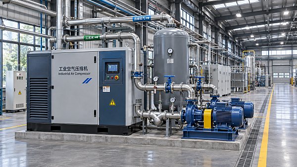
A compressor that trips on high temperature may be suffering from restricted cooling, inadequate lubrication, abnormal pressure or a misleading sensor reading. The alarm identifies a condition, not necessarily its cause. Replacing a temperature switch or adding oil before checking the operating conditions can leave the underlying fault in place and expose the machine to another shutdown.
For after-sales maintenance personnel, the immediate priorities are to protect the equipment, establish where the temperature is being measured and reconstruct what changed before the alarm. A hot discharge line on a reciprocating compressor, a high oil-injection temperature on a rotary screw unit and an elevated bearing temperature on a centrifugal machine require different investigations. The manufacturer’s limits and the instrument’s location matter more than a temperature reading considered in isolation.
Make the machine safe before diagnosing the heat
Respond to a high-temperature trip according to the site procedure and the compressor manufacturer’s instructions. Do not repeatedly reset the alarm to keep production running: a recurring trip can indicate a cooling, lubrication or mechanical problem that worsens with continued operation. If there is smoke, an unusual smell, abnormal vibration or evidence of a leak, keep personnel clear and follow the site’s emergency procedure.
Before opening guards, disconnecting lines or accessing pressurized components, isolate the relevant energy sources, secure them against unexpected restart and verify the required zero-energy state. Allow hot parts to cool and release trapped pressure through the prescribed points. Electrical equipment, stored pneumatic energy and automatic restart controls all need consideration. The U.S. Occupational Safety and Health Administration’s Control of Hazardous Energy standard, 29 CFR 1910.147, describes lockout and verification requirements for covered servicing activities; local requirements and site procedures also apply.
Record the alarm before clearing it. Capture the displayed temperature, sensor tag, operating pressure, load or control state, ambient conditions and any other active alarms. Ask whether the trip occurred during startup, sustained operation, unloading or shutdown. Those details can separate a gradual loss of cooling capacity from a fault that occurs only under a particular control condition.
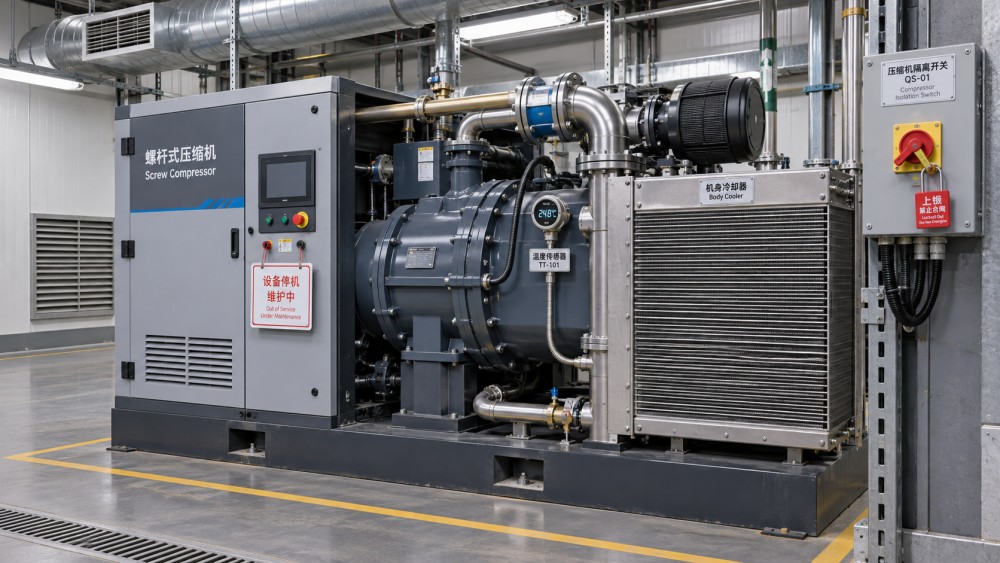
Identify which temperature is actually high
Compressor panels may display discharge gas temperature, oil temperature, bearing temperature, cooling-water temperature or several of these at once. They do not respond to the same faults in the same way. A discharge temperature increase accompanied by normal oil temperature points the investigation in a different direction from a rise in oil temperature followed by high bearing temperatures.
Compare the current reading with the machine’s normal trend at a similar load, inlet condition and ambient temperature. Check whether the value rises smoothly or jumps abruptly. A sudden implausible change may indicate a sensor, wiring or input fault, while a gradual increase can be consistent with deteriorating cooling or a change in operating conditions. Neither pattern proves the cause.
Where the equipment design permits safe verification, compare the instrument reading with an independent, suitable measuring device at the specified location. Surface measurements do not necessarily equal the temperature of the gas, oil or bearing inside the machine. Inspect the sensor mounting, wiring and controller configuration, and use the manufacturer’s procedure for calibration or replacement. A failed sensor must not be bypassed simply to restore operation.
Trace the heat back to the operating conditions
Cooling air or water is not removing enough heat
On air-cooled packages, inspect cooler surfaces, inlet and outlet openings, fan operation and airflow direction. Dust, oil film and debris can restrict airflow or insulate heat-transfer surfaces. A clean-looking front face does not guarantee that the full cooler core is clear. Check for recirculation of hot discharge air, particularly where equipment is enclosed or another heat source is nearby.
For water-cooled equipment, compare cooling-water supply temperature, pressure and flow with the manufacturer’s requirements. Fouled heat-exchanger surfaces, strainers, a partially closed valve or inadequate water supply can reduce cooling performance. A temperature difference across the cooler is useful only when interpreted alongside flow, load and design information; a single inlet or outlet reading rarely establishes whether the exchanger is performing correctly.
Clean coolers using methods compatible with their construction and site procedures. Aggressive chemicals, excessive pressure or mechanical damage can create leaks or reduce future heat transfer. After cleaning, check the readings under comparable operating conditions rather than assuming that visible dirt was the only problem.
Lubrication is inadequate or the oil circuit is restricted
Oil may lubricate bearings and gears, seal compression elements or carry heat away, depending on the compressor design. Check the oil level using the specified method and operating state. A level outside the prescribed range, an unsuitable lubricant, contamination or a restricted filter can affect the oil circuit. On machines with an oil cooler and thermostatic valve, a valve that fails to direct oil through the cooler when required may allow temperature to rise.
Examine oil pressure and filter differential pressure where instruments are fitted, but interpret them against the manufacturer’s limits and the oil temperature. Look for signs of water contamination, unusual discoloration or deposits. If the cause is not apparent, a representative oil sample and a laboratory analysis can help investigate lubricant condition and contamination. Sampling technique and comparison with the lubricant supplier’s guidance are important; an isolated result should not be treated as a complete diagnosis.
Do not mix lubricants or change viscosity solely to suppress an alarm without approval for the machine and service conditions. If contaminated oil is replaced, investigate how contamination entered and whether filters, coolers or other components also require attention.
Pressure, inlet conditions or controls have changed
Compression raises gas temperature. A higher-than-intended discharge pressure, an inlet restriction or a change in the pressure ratio can increase thermal stress, although the response depends on compressor type and controls. Check the inlet filter condition and pressure drop where measurement points are available. Confirm that inlet valves, guide vanes, unloading devices or other capacity controls move and respond as intended.
Compare discharge pressure at the compressor with the pressure required by the process. A downstream restriction, a closed valve or a control setting change may force the machine to operate differently from its intended condition. Do not adjust pressure settings or protective devices until the cause is understood and the change is authorized. Pressure relief devices are protective equipment, not a routine means of regulating discharge pressure.
Also check the inlet environment. Hot intake air, recirculated exhaust, contaminated gas or conditions outside the specified envelope can affect performance and temperatures. In a multistage machine, inadequate intercooling can raise the temperature entering a subsequent stage. Compare stage pressures and temperatures with the manufacturer’s expected operating pattern; the abnormal reading may be downstream of the component that caused it.
Mechanical condition is adding friction or disturbing flow
If cooling and process conditions appear normal, investigate mechanical symptoms. Bearing wear, misalignment, rubbing or damaged internal components may produce localized heat, vibration, noise or changes in power consumption. These symptoms are not interchangeable: a hot bearing housing does not by itself establish whether the bearing, lubrication system, alignment or measurement is at fault.
Review vibration and bearing-temperature trends where available. Inspect couplings, supports and lubrication arrangements in accordance with the maintenance procedure. Internal inspection may be necessary, but dismantling should follow the evidence and the manufacturer’s instructions. On centrifugal and other dynamic compressors, operation away from the approved operating range can also produce unstable behavior; investigate control indications and abnormal noise with the equipment supplier rather than applying checks intended for a rotary screw machine.
Use a fault record to avoid changing several things at once
A useful service record connects the symptom to the operating state and the action taken. When practical, establish a baseline before cleaning, replacing or adjusting components. If several faults are obvious, correct the unsafe conditions first; otherwise, changing one variable at a time makes it easier to identify the effective repair.
- Alarm and trend: sensor location, displayed value, trip history and time taken to reach the alarm.
- Operating state: compressor load, discharge pressure, inlet conditions, ambient temperature and relevant control positions.
- Cooling and lubrication: fan or water-system condition, cooler cleanliness, oil level, oil pressure and filter condition where applicable.
- Mechanical evidence: vibration, noise, leaks, unusual odors and any change from the machine’s established behavior.
- Repair and verification: parts replaced, settings changed, measurements after the work and remaining observations.
After maintenance, restore guards and protective devices, remove isolation only through the authorized process and check for leaks or abnormal operation during a supervised restart. Monitor the affected temperature and related pressures through the operating conditions that previously produced the fault. A short unloaded run may confirm basic function but may not reproduce a temperature rise that occurred only under sustained load. Stop the machine if the condition returns or if a protective limit is reached.
When repeated overheating points to a sizing or application mismatch
Not every recurring temperature alarm is caused by a failed component. A compressor can be mechanically sound yet operate outside the conditions assumed when the package was specified. Examples include a hotter equipment room, a changed process pressure, restricted ventilation after a layout change or a duty cycle different from the one used for the original assessment.
Reviewing those conditions is part of industrial compressor selection, whether the decision concerns a replacement machine or a proposed change to the existing installation. Maintenance records can provide practical evidence for that discussion: actual inlet temperature, pressure profile, load pattern, cooling-medium availability and the timing of previous trips are more useful than a nameplate rating alone.
The review should distinguish the compressor’s permissible operating envelope from the performance expected at the site. Check the required flow at the relevant inlet and discharge conditions, the cooling arrangement, available utilities and the effect of seasonal or process changes. A larger machine is not automatically the answer; its controls and operating range must suit the demand, and its heat rejection still has to be accommodated. Any proposed modification should be checked against the manufacturer’s documentation and applicable site requirements.
Build prevention around the failure pattern
Preventive maintenance is most effective when intervals and checks reflect the equipment and environment. A clean plant room with stable cooling water presents different risks from an installation exposed to dust, oil mist or variable ambient heat. Use the manufacturer’s service schedule as the starting point, then document site-specific findings and adjust the maintenance plan through the authorized process.
Trend the temperatures that matter for the machine alongside pressure, load and cooling conditions. A rising temperature at the same operating state can prompt inspection before a trip, while a rise explained by a hotter inlet may require an application review rather than a component replacement. Verify alarm and shutdown functions using the approved procedure; do not assume that a displayed value confirms the entire protection chain.
Close a recurring fault only when the recorded evidence supports the cause and the repaired machine has been observed under the relevant conditions. If readings remain unexplained, retain the trend data and escalate the investigation before changing protective limits or returning the compressor to unattended operation.
Facing technical bottlenecks in manufacturing or looking for more efficient industrial solutions? Leave your details below and let the engineering experts at FCSM solve them for you.
Related News
 Beijing Plan Calls for Higher Efficiency in Compressors, Pumps and Other EquipmentDr. Alistair VaughnBeijing's zero-carbon factory plan targets higher efficiency in compressors, pumps and other equipment. Explore what buyers and suppliers should verify.
 How does ISO 16889 measure hydraulic filter performance?Dr. Alistair VaughnIndustrial filtration and separation: discover how ISO 16889 measures hydraulic filter efficiency, beta ratios and contaminant capacity to help you compare filters with confidence.
 Sulzer and NABEP Agree to Support Rebuilding of Venezuelan Heavy-Oil UpgraderDr. Alistair VaughnSulzer and NABEP agree to support Venezuela’s Petrocedeño heavy-oil upgrader rebuild. Explore the supply-chain implications and key questions for suppliers.
 How to size control valves for boiler feedwaterDr. Alistair VaughnSize control valves for boiler feed with confidence. Learn to calculate Cv, assess low-load control, and prevent cavitation for reliable operation.
 How to detect leaks in industrial compressed air systemsDr. Alistair VaughnExplore compressed air system leak detection methods for industrial facilities. Find leaks safely, prioritize repairs, and verify results to reduce air loss.
 How to assess an industrial water treatment supplier's after-sales supportDr. Alistair VaughnAssess an industrial water treatment supplier’s after-sales support with practical checks for response times, technical expertise, spare parts and service costs.
 Selecting C20 Ductile Iron Pipe for Buried Water MainsDr. Alistair VaughnC20 ductile iron pipe selection starts with more than pressure class. Explore surge, soil, joint and approval checks to specify buried water mains with confidence.
 How industrial machinery retrofit trends are shaping energy efficiencyDr. Alistair VaughnExplore industrial machinery retrofit trends, from smart controls to system upgrades, and discover how to improve energy efficiency without compromising reliability.
 Gland Packing Market Forecast to Grow Through 2035 on Pump and Valve MaintenanceDr. Alistair VaughnGland packing market growth through 2035 is driven by pump and valve maintenance. Explore demand trends and opportunities in high-performance sealing.
 ComVac ASIA 2026 Opens in Shanghai, Focusing on Compressor IntelligenceDr. Alistair VaughnComVac ASIA 2026 opens in Shanghai, spotlighting intelligent compressors, digitalization and emerging opportunities in compressed air and vacuum technology.
 Industrial Compressor Overheating: Causes and Maintenance ChecksDr. Alistair VaughnIndustrial compressor selection starts with understanding overheating. Explore key causes, safety checks and maintenance tips to prevent recurring shutdowns.
 Industrial Compressor Sizing: Matching Capacity to DemandDr. Alistair VaughnMaster industrial compressor selection with practical guidance on sizing capacity, pressure, duty cycles and storage to meet demand efficiently.