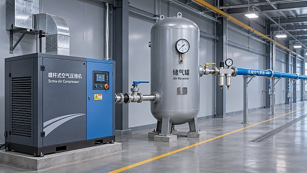
Industrial Compressor Sizing: Matching Capacity to Demand




A compressor that meets a plant’s average air demand can still fail during a short production peak. One selected only for the largest conceivable peak may spend much of its operating life running unloaded or cycling inefficiently. Matching capacity to demand requires both a flow profile and a clear definition of the pressure and air quality required at the point of use.
The distinction matters most when equipment has different operating patterns. A piston compressor serving intermittent tools faces different thermal and cycling demands from a rotary screw unit supplying a production line throughout a shift. The right comparison is not simply rated flow or motor power: it is the ability to deliver the required air at the required pressure, for the required duration, under actual site conditions.
Define the demand before choosing a machine
Start with an inventory of air consumers: production equipment, instruments, cleaning stations, pneumatic tools and any process that uses compressed air directly. Record each load’s required flow and minimum operating pressure, then identify when it runs. Nameplate consumption can be useful for an initial estimate, but actual use depends on cycle time, operating method and whether several devices run together.
For an existing installation, a time-based flow and pressure study provides a stronger foundation than a single spot reading. Include normal production, startup, shift changes and periods with unusual demand. Record compressor loading and unloading alongside receiver and point-of-use pressures. A short interval can reveal events that an hourly average conceals, such as several cylinders actuating simultaneously or a large vessel being purged.
For a new installation, build a load schedule with equipment suppliers and operators. Separate continuous loads from intermittent ones, and document which intermittent events can coincide. Do not assume that every tool operates at its maximum consumption at the same time unless the process allows that condition. Equally, do not exclude simultaneous events merely because they are inconvenient for the estimate.
Include an allowance for leakage and foreseeable changes, but keep it visible rather than hiding it in several overlapping safety factors. An oversized margin can lead to unnecessary unloading, short cycling or a compressor operating poorly at low demand. Where future expansion is uncertain, compare a staged installation with buying all anticipated capacity immediately.
Compare flow and pressure on the same basis
Compressor capacity is commonly expressed as volume flow, such as cubic feet per minute or cubic metres per hour. The number alone is insufficient. Determine whether the quoted flow is free air delivery, inlet volume flow or another defined rating, and check the reference temperature, pressure and humidity. A volume stated at line pressure cannot be compared directly with a free-air volume without conversion.
Ask suppliers to state the measurement basis and test method for capacity. ISO 1217, Displacement compressors — Acceptance tests, provides acceptance-test methods for displacement compressors; the applicable edition and any contractual deviations should be agreed in the purchase specification. This is particularly relevant when comparing screw and piston packages whose catalogues use different rating conventions. Source: International Organization for Standardization, ISO 1217.
Pressure needs the same care. Distinguish gauge from absolute pressure and identify where the value applies. The compressor discharge setpoint must accommodate pressure losses through coolers, dryers, filters, piping and other components while still meeting the minimum pressure at the most demanding user. A requirement at the tool is not automatically the correct discharge setpoint.
Measure pressure loss across treatment equipment under representative flow and maintenance conditions. A clean filter may have a smaller pressure drop than one approaching its service limit. If a distant process suffers low pressure while the main header remains adequate, investigate the branch piping, regulator and local demand before raising the pressure of the entire system.
Site conditions also affect the comparison. Inlet temperature, altitude, cooling-water temperature and ventilation can change available capacity or operating limits. For industrial compressor selection, request a performance quotation corrected to the expected installation conditions, including the proposed discharge pressure and the scope of the complete package.
Screw versus piston: examine the duty cycle
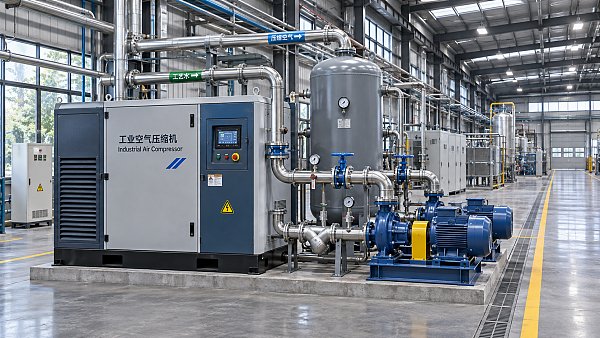
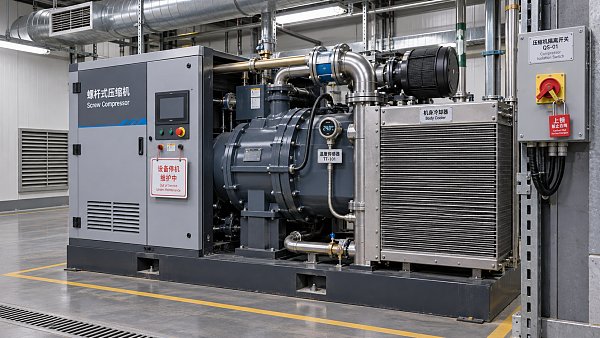
A rotary screw compressor uses meshing rotors to compress air, while a piston compressor uses reciprocating pistons in cylinders. Either technology can serve industrial duties, but the acceptable operating pattern depends on the particular machine and package. A buyer should establish continuous-running capability, permissible starts and stops, unloading behaviour and cooling requirements from the manufacturer’s documentation rather than assigning a universal duty-cycle percentage to either type.
For a piston unit, ask how the manufacturer defines duty cycle: compression time as a share of a specified period, motor running time, or another measure. Confirm the ambient temperature, discharge pressure and cooling conditions behind that rating. A compressor that repeatedly reaches its thermal limit may need a different frame, additional cooling, more storage or a different operating arrangement. A larger receiver alone does not make an unsuitable compressor suitable for continuous demand.
A rotary screw package may be designed for continuous operation, but continuous running is not the same as efficient operation at every load. A fixed-speed machine using load/unload control can continue consuming power while unloaded. A variable-speed unit can adjust output within its permitted range, yet demand below its minimum stable output may still require unloading or stopping. Actual performance depends on controls, pressure settings and the duration of low-demand periods.
Oil-injected and oil-free designs add another dimension. Air quality requirements should be established from the process, not inferred from compressor type alone. Oil-free compression does not remove the need to consider contaminants entering through intake air or downstream equipment; oil-injected systems require appropriate treatment where the application demands it. ISO 8573-1 defines compressed-air purity classes for particles, water and oil. Specify the required class and the point at which it must be achieved, rather than using the ambiguous phrase “clean air.” Source: International Organization for Standardization, ISO 8573-1, Compressed air — Part 1: Contaminants and purity classes.
Use storage to manage peaks, not conceal a capacity deficit
A receiver stores compressed air so that a brief demand can be supplied partly from storage while pressure falls within an acceptable band. It can reduce cycling and help a control system respond to a transient load. It cannot indefinitely compensate for average consumption exceeding compressor delivery.
A preliminary storage calculation needs the peak flow, peak duration, compressor contribution during the event and permitted pressure drop. Use absolute pressures and consistent temperature and volume references. The resulting theoretical volume should be checked against actual control response, pipe losses and any restrictions between the receiver and the load. A local receiver may help a large intermittent consumer, but its connection must be sized to deliver the required flow.
For example, if a process has a brief purge followed by a long recovery period, the compressor may be sized around the sustained demand while storage assists during the purge. That approach fails if the receiver cannot recharge before the next event or if the process cannot tolerate the associated pressure variation. The assumed event sequence belongs in the specification and acceptance plan.
Evaluate the complete package at the expected load profile
Compare electrical input for the compressor package, not only the motor nameplate. State whether quoted power includes the drive, cooling fans, controls, dryer and other auxiliaries. Request input power and delivered flow at several relevant operating points, including unloaded operation where applicable. A full-load figure alone cannot describe a plant that spends much of its time at partial load.
For a preliminary energy comparison, divide the operating profile into representative load intervals. Multiply measured or guaranteed package input at each interval by the expected hours, then add the results. Treat the result as an estimate: production schedules, ambient conditions and control behaviour can change actual consumption. Use the same boundaries and assumptions for every bid.
Dryer selection belongs in the capacity calculation. Some dryer arrangements consume compressed air for regeneration or have a pressure drop that changes the required compressor operating point. Ask whether the supplier’s stated net delivery accounts for that consumption. Also check condensate management, filtration, maintenance access, noise limits and the effect of a compressor outage on production.
Where continuity matters, compare one large unit with multiple staged units. Multiple machines can provide maintenance flexibility and better matching to variable demand, but only if the control system coordinates them without excessive pressure swings or competing load/unload cycles. Define whether the required capacity must remain available with one machine out of service; redundancy is a design requirement, not an automatic consequence of installing two compressors.
Turn the sizing study into an acceptance specification
A useful enquiry package gives suppliers the same demand profile, pressure basis, inlet conditions and air-quality requirement. It should identify the measurement point for delivered flow and pressure, the expected operating schedule, allowable cooling conditions and the control interfaces needed for multiple units. Ask bidders to identify exclusions and deviations explicitly.
Before purchase, agree how capacity and power will be verified, including instruments, test conditions, tolerances and corrections to reference conditions. A factory acceptance test can establish package performance under agreed conditions; a site test can then check integration, pressure losses and control response. The two tests answer different questions, especially when site temperature or the air-treatment arrangement differs from the factory setup.
During commissioning, record receiver pressure, pressure at the critical user, compressor state and package power across representative production cycles. Check that drains operate, filters are accessible, ventilation follows the supplier’s limits and safety devices are installed and tested under the applicable site procedures. Pressure vessels and protective devices should be specified and inspected against the rules applicable at the installation location.
The final sizing decision should stand up to two separate checks: the system must carry sustained demand without exceeding the compressor’s operating limits, and it must handle credible peaks without allowing the critical user’s pressure to fall below its requirement. If either check depends on an unverified assumption, resolve that assumption before treating the capacity figure as a purchase requirement.
Facing technical bottlenecks in manufacturing or looking for more efficient industrial solutions? Leave your details below and let the engineering experts at FCSM solve them for you.
Related News
 Beijing Plan Calls for Higher Efficiency in Compressors, Pumps and Other EquipmentDr. Alistair VaughnBeijing's zero-carbon factory plan targets higher efficiency in compressors, pumps and other equipment. Explore what buyers and suppliers should verify.
 How does ISO 16889 measure hydraulic filter performance?Dr. Alistair VaughnIndustrial filtration and separation: discover how ISO 16889 measures hydraulic filter efficiency, beta ratios and contaminant capacity to help you compare filters with confidence.
 Sulzer and NABEP Agree to Support Rebuilding of Venezuelan Heavy-Oil UpgraderDr. Alistair VaughnSulzer and NABEP agree to support Venezuela’s Petrocedeño heavy-oil upgrader rebuild. Explore the supply-chain implications and key questions for suppliers.
 How to size control valves for boiler feedwaterDr. Alistair VaughnSize control valves for boiler feed with confidence. Learn to calculate Cv, assess low-load control, and prevent cavitation for reliable operation.
 How to detect leaks in industrial compressed air systemsDr. Alistair VaughnExplore compressed air system leak detection methods for industrial facilities. Find leaks safely, prioritize repairs, and verify results to reduce air loss.
 How to assess an industrial water treatment supplier's after-sales supportDr. Alistair VaughnAssess an industrial water treatment supplier’s after-sales support with practical checks for response times, technical expertise, spare parts and service costs.
 Selecting C20 Ductile Iron Pipe for Buried Water MainsDr. Alistair VaughnC20 ductile iron pipe selection starts with more than pressure class. Explore surge, soil, joint and approval checks to specify buried water mains with confidence.
 How industrial machinery retrofit trends are shaping energy efficiencyDr. Alistair VaughnExplore industrial machinery retrofit trends, from smart controls to system upgrades, and discover how to improve energy efficiency without compromising reliability.
 Gland Packing Market Forecast to Grow Through 2035 on Pump and Valve MaintenanceDr. Alistair VaughnGland packing market growth through 2035 is driven by pump and valve maintenance. Explore demand trends and opportunities in high-performance sealing.
 ComVac ASIA 2026 Opens in Shanghai, Focusing on Compressor IntelligenceDr. Alistair VaughnComVac ASIA 2026 opens in Shanghai, spotlighting intelligent compressors, digitalization and emerging opportunities in compressed air and vacuum technology.
 Industrial Compressor Overheating: Causes and Maintenance ChecksDr. Alistair VaughnIndustrial compressor selection starts with understanding overheating. Explore key causes, safety checks and maintenance tips to prevent recurring shutdowns.
 Industrial Compressor Sizing: Matching Capacity to DemandDr. Alistair VaughnMaster industrial compressor selection with practical guidance on sizing capacity, pressure, duty cycles and storage to meet demand efficiently.