Industrial Machinery Warning Signs That Point to Cavitation




When Warning Signs in Industrial Machinery Mean More Than Wear
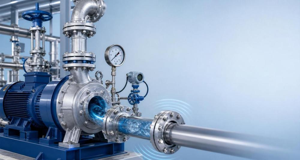
Unusual sound, unstable pressure, and falling output rarely appear without a cause in industrial machinery.
In fluid-handling systems, those signals often point to cavitation before visible damage is found.
That matters because cavitation does not stay a small hydraulic issue for long.
It can erode impellers, disturb valve control, shorten seal life, and create misleading maintenance records.
Across process plants, utilities, water treatment lines, and heavy manufacturing, the same symptom can mean different risks.
A pump feeding a cooling loop behaves differently from one handling hot chemicals or abrasive wastewater.
FCSM follows these differences closely because reliable industrial machinery depends on understanding fluid behavior in real operating conditions.
The useful approach is not simply to ask whether cavitation exists.
The better question is where it starts, how it appears, and which operating context makes it dangerous faster.
Different Operating Contexts Change the Meaning of the Same Symptom
Cavitation begins when local pressure drops below vapor pressure and vapor bubbles collapse downstream.
Yet in industrial machinery, the trigger is rarely identical from site to site.
Low suction head is a common reason, but not the only one.
Temperature shifts, throttled valves, clogged strainers, off-design flow, and poor piping layout all change the picture.
In practical terms, a rattling pump on a cold-water utility line may survive longer than a similar unit in hot condensate service.
The sound may resemble gravel in both cases, but the collapse intensity and material attack can differ sharply.
This is why industrial machinery diagnostics should connect process conditions with equipment behavior, not just vibration readings.
FCSM’s fluid intelligence work often treats cavitation as a system issue first, then a component issue.
The signs that deserve immediate attention
- Sharp crackling or gravel-like noise near the pump casing or valve trim
- Vibration that rises during flow changes rather than staying constant
- Pressure fluctuations at suction or discharge points
- Unexpected drops in flow, head, or energy efficiency
- Frequent seal leakage, bearing distress, or recurring impeller damage
- Surface pitting on metal parts exposed to fast local pressure transitions
In Pump-Dominated Processes, Cavitation Usually Starts as a Stability Problem
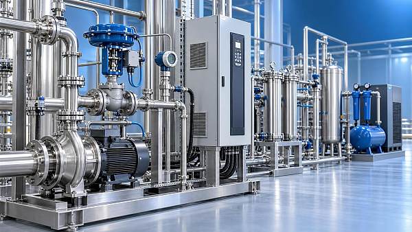
Centrifugal pump systems remain the most common place where industrial machinery warning signs reveal cavitation early.
Chemical transfer, boiler feed, cooling water circulation, and municipal treatment all show this pattern.
At first, the problem may look like inconsistent throughput or control drift.
Operators may raise speed, close valves, or schedule motor checks without addressing suction conditions.
That response often pushes industrial machinery deeper into the unstable zone.
More common in real plants is partial blockage on the suction side, a liquid level change, or a warmer-than-normal process stream.
Each one reduces the margin between available and required NPSH.
Where pumps run continuously, the key judgment is not just whether cavitation exists today.
It is whether the condition appears during startups, batch transitions, seasonal temperature swings, or peak demand.
Those short periods often create the damage that later looks like routine mechanical wear.
What to check in these lines
Review suction pressure trend data, liquid temperature, tank level, and strainer differential pressure together.
Then compare actual flow with the pump curve, not only with target production numbers.
If industrial machinery is repeatedly pushed far from best efficiency point, cavitation risk rises quickly.
Control Valves and High-Velocity Restrictions Create a Different Cavitation Pattern
Not every cavitation problem begins inside a pump.
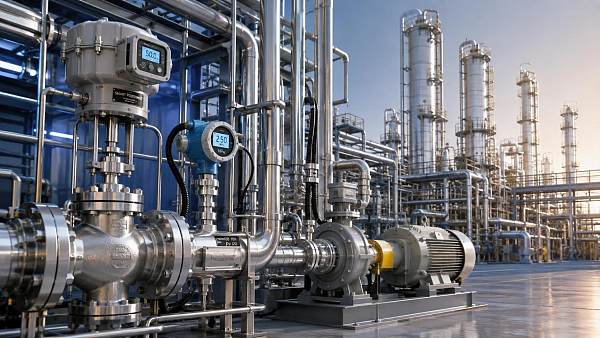
In many industrial machinery networks, the first damage appears at control valves, orifice sections, and other throttling points.
This is especially relevant in pressure letdown duties, condensate recovery, and process recirculation loops.
The visible symptom is often noise, but the deeper issue is local pressure collapse around the trim.
A valve may still regulate flow acceptably while internal erosion is already progressing.
That creates a false sense of stability in industrial machinery inspections focused only on control response.
In these applications, the judgment point shifts from suction conditions to pressure drop profile and trim design.
Severe service valves, multistage trims, and proper flashing evaluation matter more than generic valve sizing.
A system that looks acceptable on paper can still fail if real fluid properties differ from clean-water assumptions.
Wastewater, Filtration, and Harsh Media Need a More Careful Diagnosis
In filtration and separation systems, cavitation can hide behind solids-related wear.
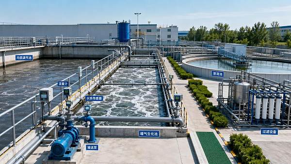
That makes diagnosis harder in industrial machinery handling sludge, brine, slurry, or contaminated liquids.
A rough impeller surface or damaged casing does not automatically prove abrasive attack alone.
In actual service, blocked suction screens, viscosity changes, and recirculation pockets may trigger cavitation first.
Then suspended solids accelerate the damage.
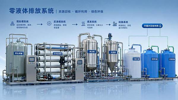
This combined failure mode is common in industrial machinery tied to ZLD, municipal treatment, and recycled process water.
The practical mistake is treating every roughened metal surface as a material problem.
Material upgrades help, but they do not restore hydraulic stability.
A more reliable response is to examine flow path cleanliness, suction piping geometry, and actual duty cycle changes.
Where Industrial Machinery Teams Often Misread Cavitation
Several misjudgments appear repeatedly across plants.
- Treating noise as a bearing issue without checking process-side pressure behavior
- Relying on nameplate capacity while ignoring actual fluid temperature and density
- Assuming a replacement pump will solve the issue without reviewing piping losses
- Judging valve performance by stroke response while internal trim damage continues
- Looking only at purchase cost, then missing repeated downtime and spare parts use
In industrial machinery management, cavitation is often misread because the first symptom appears mechanical while the root cause is hydraulic.
That is why FCSM consistently links component health with CFD insight, operating data, and process context.
Without that link, teams may repair damage repeatedly while the triggering condition stays untouched.
A Practical Path to Better Fit and Lower Risk
The most effective response starts with a simple discipline: verify the operating scene before selecting the remedy.
For industrial machinery, that means collecting several data points at the same time, not in isolation.
- Map noise, vibration, pressure, flow, and temperature during normal and upset conditions
- Check whether the problem appears at startup, high load, low tank level, or seasonal heat
- Compare installed equipment against actual duty, not only design duty
- Review valve pressure drops and pump suction losses in the same system model
- Estimate maintenance impact over time, including seals, impellers, trim, and energy penalties
Some cases need piping modification or suction improvement.
Others need impeller resizing, speed adjustment, different trim architecture, or better monitoring logic.
The right answer depends on how that industrial machinery actually works across its lifecycle.
A useful next step is to document the exact operating window, compare failure timing with process events, and build a scene-based checklist for future reviews.
That approach usually reveals whether cavitation is an isolated defect or a broader reliability pattern already forming.
Related News
 What drives industrial wastewater treatment cost per cubic meter?Dr. Alistair VaughnIndustrial wastewater treatment cost per cubic meter depends on influent load, effluent targets, energy, technology, and sludge disposal. Explore the key cost drivers.
 How to verify CE compliance for fluid separation equipmentDr. Alistair VaughnFluid separation equipment CE verification made practical: learn how to check declarations, risk assessments, technical files, pressure safety, and installation readiness.
 Separation equipment trends reshaping industrial wastewater treatmentDr. Alistair VaughnSeparation equipment trends are reshaping industrial wastewater treatment through smarter membranes, modular systems, digital monitoring, and resource recovery strategies.
 When stainless steel separation equipment is the right choice for hygienic processesDr. Alistair VaughnStainless steel separation equipment: discover when hygienic design, corrosion resistance, CIP cleanability, and lifecycle reliability make it the smart choice.
 What to assess before choosing a process industry automation supplierDr. Alistair VaughnChoose a process industry automation supplier with confidence. Assess engineering depth, lifecycle reliability, digital integration, energy performance, and safety before you buy.
 How process control innovation in refineries reduces unplanned shutdownsDr. Alistair VaughnDiscover how process control innovation in refineries detects early deviations, improves valve and equipment reliability, and helps prevent costly unplanned shutdowns.
 What should a zero liquid discharge systems integrator include in its proposal?Dr. Alistair VaughnZero liquid discharge systems integrator proposal checklist: compare guarantees, utilities, scope, controls, waste handling, and lifecycle risk before award.
 Industrial wastewater treatment plant design: sizing for flow and loadDr. Alistair VaughnIndustrial wastewater treatment plant design guide: size systems for peak flow, pollutant loads, reliability, compliance, and lower lifecycle costs.
 Can predictive maintenance and machinery diagnostics prevent downtime?Dr. Alistair VaughnPredictive maintenance machinery diagnostics help reduce unplanned downtime by detecting early equipment issues, improving reliability, and enabling smarter maintenance decisions.
 Can a digital transformation machinery platform cut unplanned downtime?Dr. Alistair VaughnDiscover how a digital transformation machinery platform connects asset data, maintenance workflows, and process insights to reduce unplanned downtime.
 How water treatment equipment sizing affects operating costsDr. Alistair VaughnWater treatment equipment sizing shapes energy, chemical, and maintenance costs. Learn how to balance flow, pressure, recovery, and reliability for efficient operation.
 When does food processing automation justify the upfront investment?Dr. Alistair VaughnIndustrial automation solutions for food processing: discover when automation delivers measurable ROI through higher throughput, lower waste, reliable utilities, and stronger food safety control.