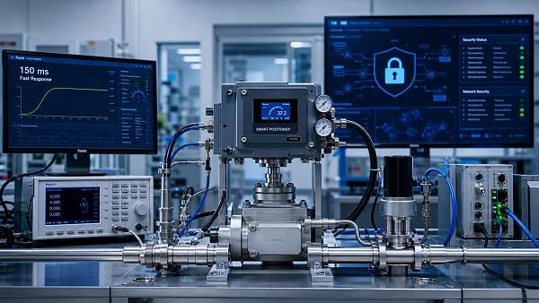
How fluid control digitalization improves valve maintenance planning




How Fluid Control Digitalization Improves Valve Maintenance Planning
Fluid control digitalization is reshaping how maintenance teams plan valve inspections, diagnose performance issues, and avoid unplanned process interruptions. For years, many valve programs have relied on fixed inspection intervals, operator observations, and emergency repairs after a control loop begins to drift. That approach can keep a plant running, but it does not always direct limited maintenance time toward the valves that present the greatest operational or safety risk.
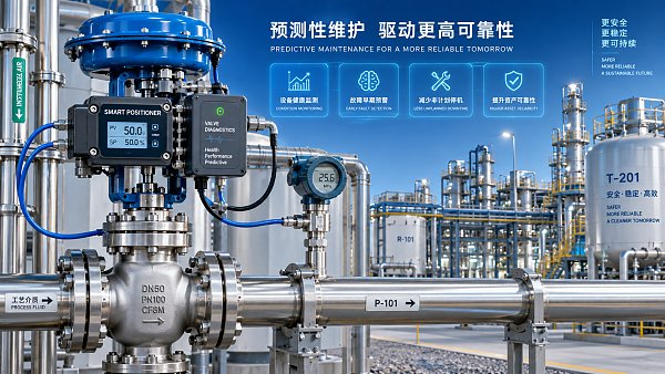
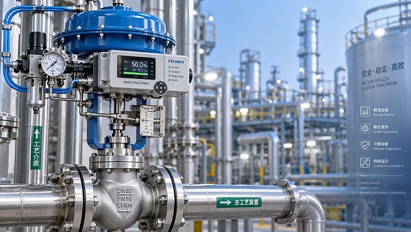
Digital tools change the basis for decision-making. A smart positioner, actuator diagnostic module, historian, and maintenance management system can turn a valve from a largely invisible mechanical asset into a source of operating evidence. Maintenance planners can see whether a valve is stroking normally, whether its friction is increasing, whether supply air quality may be affecting response, or whether the process is forcing the trim into damaging operating conditions. The objective is not to replace practical field judgment. It is to give that judgment better timing and better context.
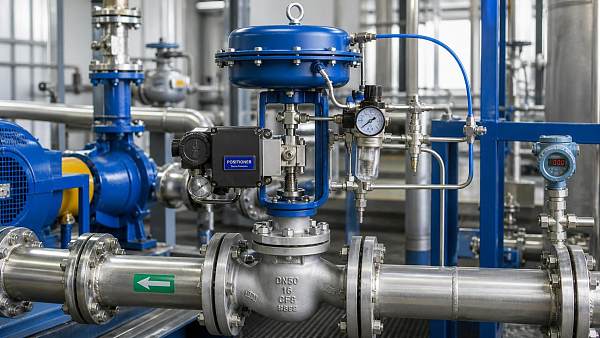
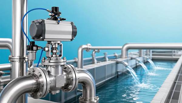
This matters most in plants where control valves act as the throats of automated pipe networks: chemical processing, water treatment, refining, power generation, food production, pulp and paper, pharmaceutical utilities, and industrial separation systems. A valve may be physically small compared with a pump, compressor, reactor, or filtration train, yet a poorly performing valve can destabilize pressure, level, temperature, flow, and product quality across the wider process.
Moving beyond calendar-based valve maintenance
Time-based maintenance remains useful for statutory checks, shutdown planning, and assets with predictable wear patterns. The problem appears when all valves receive broadly the same attention regardless of duty. A clean-water isolation valve that moves infrequently should not necessarily compete for workshop capacity with a high-cycle steam control valve, a corrosive slurry throttling valve, or a pressure-control valve operating near critical flow conditions.
Fluid control digitalization enables a more selective model: inspect and intervene according to condition, consequence, and operating duty. Instead of asking only, “When was this valve last serviced?” planners can ask more useful questions:
- Has the valve’s travel response changed compared with its normal signature?
- Is the controller demanding repeated small corrections because of deadband or stiction?
- Has the valve spent extended periods near the closed or wide-open position, suggesting poor sizing or a changed process requirement?
- Are pressure drop, noise, vibration, or downstream conditions consistent with cavitation, flashing, choking, or excessive aerodynamic noise?
- Would failure affect a safety function, production bottleneck, emissions limit, energy use, or maintenance access window?
These questions help distinguish a nuisance alarm from a developing reliability problem. They also prevent the opposite mistake: dismantling a healthy valve simply because a calendar interval has elapsed. In facilities where outages are tightly scheduled, avoiding unnecessary intrusive work can be almost as valuable as detecting a genuine fault earlier.
What digital valve data can reveal
Not every valve needs the same level of instrumentation. A critical modulating valve with a smart electro-pneumatic positioner can provide more diagnostic depth than a manual utility valve. Even so, the useful principle is consistent: combine mechanical evidence with process evidence. Position feedback by itself may show that a valve reached its commanded travel. It does not prove that the valve controlled the process efficiently or that the trim remained suitable for the actual pressure drop.
A practical digital record often includes valve travel, command signal, cycle count, travel deviation, actuator pressure, supply-air condition where available, and diagnostic alerts from the positioner. It becomes far more valuable when linked with process variables such as flow, upstream and downstream pressure, temperature, control-loop output, and alarm history. A rising travel deviation may point to packing friction, stem issues, actuator problems, or linkage wear. Frequent oscillation may be caused by the valve, but it can also originate in poor tuning, an unstable process, pressure disturbances, or an incorrectly sized valve. Digitalization should make technicians more precise, not encourage them to blame every loop problem on the final control element.
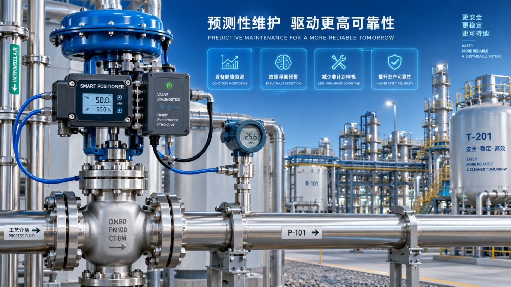
Valve signatures are especially helpful after commissioning, overhaul, trim replacement, or a known-good field test. That reference condition gives future diagnostics something meaningful to compare against. Without a baseline, a dashboard may display trends but still leave planners unsure whether a measured friction level or response time is normal for that actuator, packing arrangement, process medium, and ambient condition.
Signals should lead to maintenance decisions, not just more alarms
The common failure of a digital maintenance project is not missing sensors; it is creating data with no action path. A maintenance planner needs a clear rule for what happens after a diagnostic alert. Is the issue recorded for the next route inspection? Does it trigger a field check within days? Does it require engineering review before the next shutdown? Or does it justify a controlled intervention because the process consequence is high?
The table is deliberately not a fault dictionary. The same symptom can have several causes. Good planning retains a verification step, particularly where a valve serves a hazardous medium, operates at high pressure, or forms part of a protective function.
Prioritizing valves by risk and process consequence
A digital maintenance system becomes useful when it helps create a defensible backlog. Ranking valves only by alarm count is rarely enough. A valve that cycles often in a non-critical utility service may generate more events than a rarely moved emergency isolation valve whose failure would have serious consequences. The priority model should therefore combine condition indicators with functional criticality.
For each important valve, maintenance teams should establish a minimum asset record: tag number, service, body and trim materials, actuator type, fail position, positioner model, process medium, design and current operating conditions, maintenance history, spare-part status, and isolation requirements. Where available, include the control narrative and any safety or environmental role. This sounds basic, but many plants hold this information across drawings, spreadsheets, old work orders, and individual experience. Digitalization is most effective when it connects those records rather than merely adding another screen.
The criticality conversation often exposes maintenance blind spots. A control valve may have a low direct replacement cost but be difficult to isolate, require a special alloy trim, or sit in a service where an upset damages upstream pumps, separators, or compressors. Conversely, some valves can be monitored with relatively simple route-based checks because failure has limited consequence and replacement is straightforward. The right maintenance plan is rarely one uniform standard applied across the entire valve population.
Connecting valve health to the wider fluid system
Valve maintenance cannot be separated from fluid dynamics. A valve may appear mechanically sound while the process is subjecting it to damaging conditions. For liquid service, large pressure reduction across a throttling element can produce cavitation or flashing depending on the fluid and downstream pressure. For gas and steam service, high velocity, aerodynamic noise, vibration, and pressure recovery characteristics may affect trim life and adjacent piping. Those conditions are not resolved simply by recalibrating a positioner.
This is where integrated operational data changes planning quality. If pump operating points shift, a control valve may see a new differential pressure profile. If filters foul, separator performance changes, or compressor capacity control is modified, downstream control duties can also change. A valve’s apparent maintenance issue may therefore be a system issue. Before ordering a new trim or scheduling repeated packing replacement, compare the valve’s actual duty with the conditions assumed in its selection documentation. That review may reveal a mismatch in flow range, pressure drop, fluid properties, or control strategy.
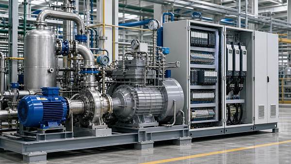
FCSM follows this connected view across industrial pumps, high-pressure plunger pumps, smart pneumatic control valves, compressor systems, and filtration and separation equipment. The point is not to treat every asset as part of one large dashboard. It is to understand that the “blood vessels and respiratory systems” of industry influence one another. For maintenance teams, that perspective helps distinguish a valve failure mechanism from a process condition that will quickly damage the replacement as well.
Building a workable digital maintenance workflow
The most reliable implementation usually starts with a limited group of critical or troublesome valves rather than a plant-wide instrumentation campaign. Select assets with recurring maintenance burden, unstable control, high production consequence, difficult access, or known severe service. Confirm that tag structures are consistent between the control system, historian, and maintenance records. Then agree on a small number of condition indicators that technicians and planners can actually use.
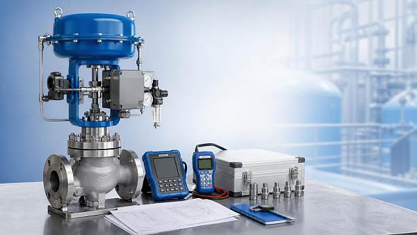
A practical sequence may include establishing baseline signatures, reviewing historical work orders, setting alert thresholds with engineering input, and defining who reviews each class of exception. Technicians should be able to attach field findings to the same asset record: packing condition, air leaks, stem corrosion, travel checks, calibration results, trim observations, and photographs where site procedures permit. Over time, this creates a record that supports better shutdown scope decisions and more accurate spare planning.
Do not overlook cybersecurity, data ownership, and instrument maintenance. Networked positioners and gateways need appropriate access control and lifecycle support. Diagnostic quality also depends on healthy tubing, clean instrument air, correct calibration, and sound tag management. A digital system cannot compensate for neglected fundamentals. It can, however, make weaknesses visible sooner.
A more useful definition of predictive maintenance
Predictive maintenance is sometimes presented as a promise that software will identify the exact day a valve will fail. Real industrial work is less certain. Wear rates depend on service severity, material compatibility, cycling, contaminants, installation quality, operating transients, and the accuracy of available data. The more realistic benefit is earlier recognition of deviation, stronger prioritization, and fewer surprises during an outage or production upset.
For a maintenance planner, that is already a substantial improvement. A work order can be prepared with the likely failure mode in mind. Required isolation, lifting access, special tools, trim kits, actuator seals, positioner checks, and vendor support can be reviewed before the valve is opened. Operations can be involved at the right time rather than asked for an emergency window after control performance has already deteriorated.
The strongest valve maintenance plans combine field craft with digital evidence and process understanding. Start by identifying the valves whose failure would be hardest to absorb. Confirm that their asset data and baseline behavior are credible. Then use fluid control digitalization to turn changing conditions into planned work—not more alarms, and not blind confidence in an algorithm. That discipline supports reliable control, safer interventions, and more energy-conscious operation across the wider fluid system.
Related News
 How fluid control digitalization improves valve maintenance planningProcess Control ArchitectFluid control digitalization helps teams prioritize valve maintenance, reduce unplanned downtime, and improve reliability with actionable condition data.
 How smart valve positioners improve process control valve accuracyProcess Control ArchitectDiscover how smart positioners improve process control valve accuracy, reduce friction-related errors, enhance stability, and enable predictive maintenance.
 How to evaluate a valve automation supplier before placing an orderProcess Control ArchitectChoose a valve automation supplier with confidence. Learn how to assess engineering capability, compatibility, testing, lead times, and lifecycle support before ordering.
 How Does Industrial Automation Change Valve Specification Requirements?Process Control ArchitectHow does industrial automation change valve specification needs? Discover smarter sizing, diagnostics, protocols, fail-safe design, and lifecycle strategies for reliable control.
 Retrofit vs replacement automation: which option minimizes downtime?Process Control ArchitectRetrofit vs replacement automation: compare downtime, integration risk, lifecycle costs, and phased execution to protect uptime and modernize with confidence.
 When smart pneumatic control valves improve water treatment stabilityProcess Control ArchitectSmart pneumatic control valves for water treatment improve flow precision, dosing consistency, diagnostics, and plant stability. Learn how to select the right solution.
 When predictive maintenance for process valves pays off in plant operationsProcess Control ArchitectPredictive maintenance for process valves can cut downtime, reduce energy loss, and boost reliability. Learn when it pays off in plant operations—and how to justify the investment.
 Revised EN 14382:2026 Adds EMC Immunity Test for Smart Valve Positioners in EU ExportsProcess Control ArchitectEN 14382:2026 now mandates EMC immunity testing for Smart Valve Positioners, reshaping EU export compliance for valve OEMs and integrators. Learn what changed and how to prepare.
 FDA Tightens Import Rules for Smart Valve PositionersProcess Control ArchitectSmart valve positioners now face stricter FDA import rules. Learn how IEC 61508 SIL2 or UL 61508 documentation affects U.S. clearance, suppliers, and compliance planning.
 EN 14382:2026 Raises EU Entry Bar for Smart PositionersProcess Control ArchitectEN 14382:2026 raises the EU entry bar for Smart Valve Positioners with a 150 ms step response cap and IEC 62443-4-2 cybersecurity checks. Learn what exporters, buyers, and compliance teams must do before Nov 1, 2026.
 High-Precision Stainless Steel Control Valves for Corrosive Process LinesProcess Control ArchitectHigh-precision control valves stainless steel solutions improve corrosion resistance, flow stability, and safety in demanding process lines. Discover how to reduce downtime and boost control accuracy.
 How a Valve Performance Consultant Improves Uptime and Control AccuracyProcess Control ArchitectValve performance consultant insights to improve uptime, control accuracy, and energy efficiency. Learn how targeted diagnostics solve hidden valve issues across process systems.