Valve Positioner Technology: Setup Errors to Avoid




Even the most advanced valve positioner technology can underperform when setup basics are missed. For after-sales maintenance teams, small calibration, air supply, or signal-matching errors often lead to unstable control, excess wear, and costly downtime. This guide highlights the setup mistakes to avoid so you can improve response accuracy, restore process reliability, and keep smart control valves operating at peak efficiency.
Why does valve positioner technology fail after installation even when the hardware is sound?
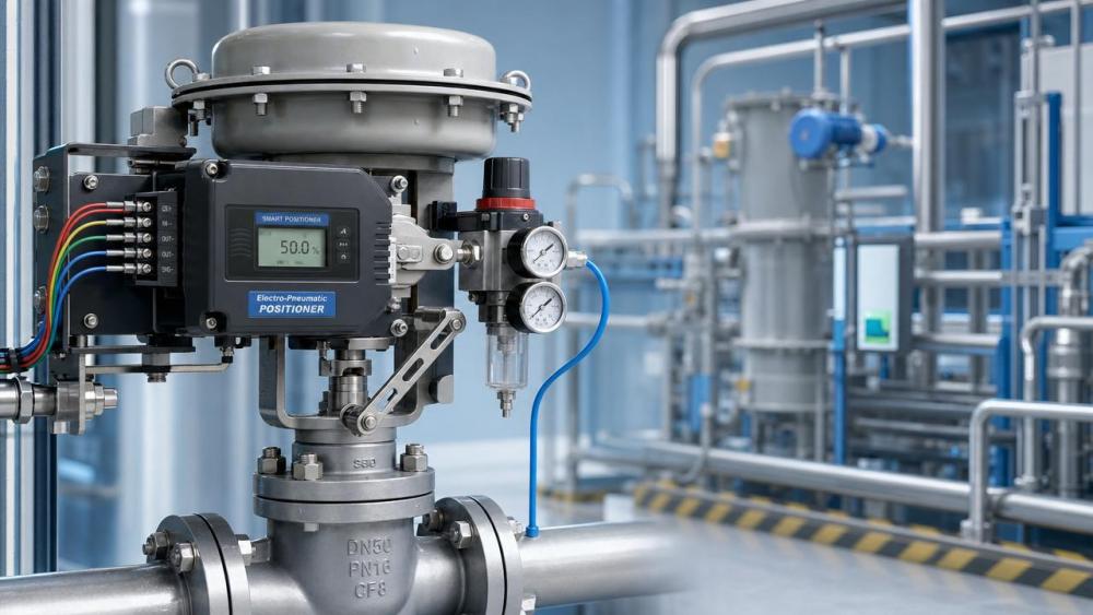
In many plants, the positioner is blamed first, but the real problem is often setup discipline. After-sales maintenance staff usually inherit mixed site conditions: inconsistent instrument air quality, undocumented stroke settings, aging actuators, and control loops tuned for a previous valve package.
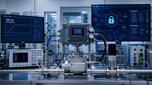
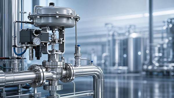
That is why valve positioner technology should be treated as part of a full control assembly, not an isolated accessory. A smart electro-pneumatic positioner only performs well when signal input, actuator mechanics, supply pressure, feedback linkage, and process dynamics are aligned.
For FCSM, this is a familiar pattern across chemical processing, water treatment, power utilities, compressor skids, and fluid separation systems. In each case, a small setup error can cascade into unstable throttling, cavitation risk, compressor loading imbalance, or poor membrane feed control.
- Positioner setup is often rushed during restart windows, so zero and span are accepted without dynamic testing.
- Maintenance teams may replace a failed unit with a similar model, but leave incompatible actuator action or split-range logic unchanged.
- Air compressor and filtration issues upstream can quietly degrade response, even when the valve assembly looks normal during manual checks.
Which setup errors in valve positioner technology cause the most field problems?
The most common mistakes are not exotic. They are basic configuration mismatches that distort travel feedback, slow response, or create hunting around the setpoint. The table below summarizes high-frequency issues seen by maintenance teams in general industry environments.
These issues matter because valve positioner technology controls the final movement that the DCS or PLC expects to be precise. If travel and command do not match, every upstream control strategy becomes less reliable, no matter how advanced the automation platform is.
Signal mismatch is more common than many teams expect
A 4–20 mA input problem is not always caused by bad wiring. It can come from wrong input scaling, split-range configuration left from an older loop, or a positioner expecting a different characterization mode. In digital positioners, a wrong local setting may look harmless until the valve operates across the full process range.
Mechanical friction can hide behind a “successful” calibration
If packing is too tight, the stem is slightly bent, or the actuator diaphragm is aging, auto setup may complete but control quality will still suffer. Maintenance personnel should always compare static calibration results with dynamic stroke behavior under live air and realistic load conditions.
How should after-sales teams check valve positioner technology before restarting the process?
A structured pre-start routine saves far more time than repeated troubleshooting later. In high-duty fluid systems, one missed check can affect pumps, compressors, separators, and downstream pressure balance. The aim is not just to make the valve move, but to make it move predictably.
- Confirm nameplate data, actuator type, fail action, stroke length, and mounting geometry before energizing the positioner.
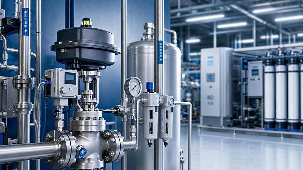
- Verify clean and dry instrument air. Check regulator setting, filter condition, and whether supply pressure matches actuator requirements.
- Inspect linkage, stem travel, bench set, and packing friction manually before starting auto-calibration.
- Run auto setup, then validate zero, span, and direction with independent command points such as 0%, 25%, 50%, 75%, and 100%.
- Observe actual response time, overshoot, and position stability under process-representative conditions, not only in maintenance mode.
This workflow is especially important in smart pneumatic control valves used near cavitation limits, high differential pressure zones, or compressor recycle lines. FCSM consistently emphasizes that final control element reliability starts with disciplined setup, not just component replacement.
What parameters deserve the closest attention during setup and verification?
When evaluating valve positioner technology, after-sales teams need a practical parameter view rather than a catalog-only view. The table below focuses on setup-critical items that directly affect field performance and maintainability.
For plants handling corrosive liquids, compressed gases, wastewater, or thermal fluids, these parameters influence more than valve movement. They influence energy use, process stability, noise generation, and equipment life across the wider system.
How do setup mistakes differ by application scenario?
Valve positioner technology behaves differently depending on the duty. A cooling water control valve, a steam letdown valve, and a membrane feed throttling valve may use similar hardware, but their failure patterns in setup are not the same.
- Chemical dosing and corrosive service: Teams often focus on trim material and overlook air line contamination. Sticky motion and delayed correction then appear as process variability.
- Water and wastewater treatment: Long idle periods may lead to linkage stiffness. A positioner calibrated after manual stroking can still drift once frequent modulation resumes.
- Compressor and pneumatic utility systems: Poor positioner tuning can amplify recycle loop oscillation, creating avoidable power consumption and unstable header pressure.
- Filtration and separation skids: Valves that regulate differential pressure or backwash timing need repeatability more than raw speed. Overaggressive tuning often causes unnecessary cycling.
This application-level view is central to FCSM’s fluid machinery perspective. A control valve does not operate alone. Its setup quality influences pump loading, air compressor duty, separation efficiency, and even maintenance planning under decarbonization targets.
Should you recalibrate, repair, or replace the positioner?
After-sales teams are often forced to make quick decisions with limited shutdown time. A disciplined comparison helps avoid replacing a healthy device when the root cause sits elsewhere, or wasting time on recalibration when the hardware is already degraded.
A replacement decision should also consider communication protocol needs, spare strategy, maintenance skill level, and how quickly the plant can restore compliance with its internal reliability targets.
What standards, documentation, and service records should maintenance teams keep?
Good valve positioner technology management is not only a commissioning task. It is a documentation task. In regulated or high-risk process environments, traceable setup records reduce repeat failures and support safer handover between project, operations, and service teams.
Recommended records
- As-left and as-found calibration values, including zero, span, action direction, and tuning settings.
- Actuator model, spring range, bench set, stroke length, and fail-safe action confirmation.
- Instrument air quality checks, regulator settings, filter replacement dates, and upstream compressor condition notes.
- Loop test results at multiple command points with observed response time and stability comments.
Where relevant, teams may also review general standards or plant specifications tied to control valve performance, instrument air quality, electrical area classification, and maintenance procedures. The exact standard set depends on site policy and service environment, so records should remain practical and traceable.
FAQ: common questions about valve positioner technology in maintenance work
How often should valve positioner technology be recalibrated?
There is no universal interval. Recalibration is usually triggered by shutdown maintenance, actuator repair, control instability, diagnostic alerts, or drift seen during proof testing. Critical service valves often deserve condition-based checks during routine inspections rather than waiting for a full failure event.
Can a smart positioner solve poor valve sizing or severe stiction?
No. Smart diagnostics can help reveal these problems, but they cannot fully compensate for a badly sized valve or major mechanical friction. If the valve is oversized, undersized, or mechanically compromised, setup improvements alone will not deliver stable control.
What is the fastest field check when the valve does not track the command signal?
Start with four basics: input signal value, actuator action direction, actual supply pressure, and free mechanical travel. These checks isolate many issues faster than jumping directly into advanced diagnostics menus or immediate parts replacement.
Why does the valve look stable in manual mode but hunt in automatic control?
Manual mode removes the real process feedback dynamics. In automatic operation, the positioner interacts with loop tuning, valve gain, pressure fluctuations, and friction breakaway. Hunting may therefore point to tuning mismatch, air supply variation, or process-side disturbance rather than a basic calibration error alone.
Why choose us when you need practical guidance on valve positioner technology?
FCSM supports maintenance-driven decision making from a wider fluid control perspective. We do not look at a positioner as a standalone device only. We connect control valve behavior with pump stability, compressor efficiency, filtration duty, process decarbonization, and digital maintenance strategy.
If your team is handling recurring stroke errors, unstable smart pneumatic control valves, replacement planning, or service documentation gaps, you can consult us for targeted support in the areas that matter operationally.
- Parameter confirmation for actuator type, supply pressure, feedback travel, and control signal compatibility.
- Selection guidance for smart positioner functions, maintenance-friendly configurations, and plant-specific control requirements.
- Advice on delivery timing, spare strategy, replacement planning, and practical alternatives when shutdown windows are tight.
- Support for documentation expectations, application matching, and broader fluid machinery reliability considerations.
When you contact us, share your valve type, actuator details, process medium, signal format, air supply condition, and the symptoms observed in the field. That makes it easier to discuss setup corrections, selection options, certification-related concerns, sample evaluation needs, and quotation communication with less delay and fewer trial-and-error interventions.
Related News
 How fluid control digitalization improves valve maintenance planningProcess Control ArchitectFluid control digitalization helps teams prioritize valve maintenance, reduce unplanned downtime, and improve reliability with actionable condition data.
 How smart valve positioners improve process control valve accuracyProcess Control ArchitectDiscover how smart positioners improve process control valve accuracy, reduce friction-related errors, enhance stability, and enable predictive maintenance.
 How to evaluate a valve automation supplier before placing an orderProcess Control ArchitectChoose a valve automation supplier with confidence. Learn how to assess engineering capability, compatibility, testing, lead times, and lifecycle support before ordering.
 How Does Industrial Automation Change Valve Specification Requirements?Process Control ArchitectHow does industrial automation change valve specification needs? Discover smarter sizing, diagnostics, protocols, fail-safe design, and lifecycle strategies for reliable control.
 Retrofit vs replacement automation: which option minimizes downtime?Process Control ArchitectRetrofit vs replacement automation: compare downtime, integration risk, lifecycle costs, and phased execution to protect uptime and modernize with confidence.
 When smart pneumatic control valves improve water treatment stabilityProcess Control ArchitectSmart pneumatic control valves for water treatment improve flow precision, dosing consistency, diagnostics, and plant stability. Learn how to select the right solution.
 When predictive maintenance for process valves pays off in plant operationsProcess Control ArchitectPredictive maintenance for process valves can cut downtime, reduce energy loss, and boost reliability. Learn when it pays off in plant operations—and how to justify the investment.
 Revised EN 14382:2026 Adds EMC Immunity Test for Smart Valve Positioners in EU ExportsProcess Control ArchitectEN 14382:2026 now mandates EMC immunity testing for Smart Valve Positioners, reshaping EU export compliance for valve OEMs and integrators. Learn what changed and how to prepare.
 FDA Tightens Import Rules for Smart Valve PositionersProcess Control ArchitectSmart valve positioners now face stricter FDA import rules. Learn how IEC 61508 SIL2 or UL 61508 documentation affects U.S. clearance, suppliers, and compliance planning.
 EN 14382:2026 Raises EU Entry Bar for Smart PositionersProcess Control ArchitectEN 14382:2026 raises the EU entry bar for Smart Valve Positioners with a 150 ms step response cap and IEC 62443-4-2 cybersecurity checks. Learn what exporters, buyers, and compliance teams must do before Nov 1, 2026.
 High-Precision Stainless Steel Control Valves for Corrosive Process LinesProcess Control ArchitectHigh-precision control valves stainless steel solutions improve corrosion resistance, flow stability, and safety in demanding process lines. Discover how to reduce downtime and boost control accuracy.
 How a Valve Performance Consultant Improves Uptime and Control AccuracyProcess Control ArchitectValve performance consultant insights to improve uptime, control accuracy, and energy efficiency. Learn how targeted diagnostics solve hidden valve issues across process systems.