CFD Simulation Analysis for Valve Flow Problems




CFD Simulation Analysis for Valve Flow Problems
For valve systems, flow behavior rarely stays simple once pressure, temperature, and media conditions start shifting.
That is why CFD simulation analysis has become a practical decision tool, not just an engineering exercise.
It shows what happens inside the valve body before a prototype is built or a shutdown is scheduled.
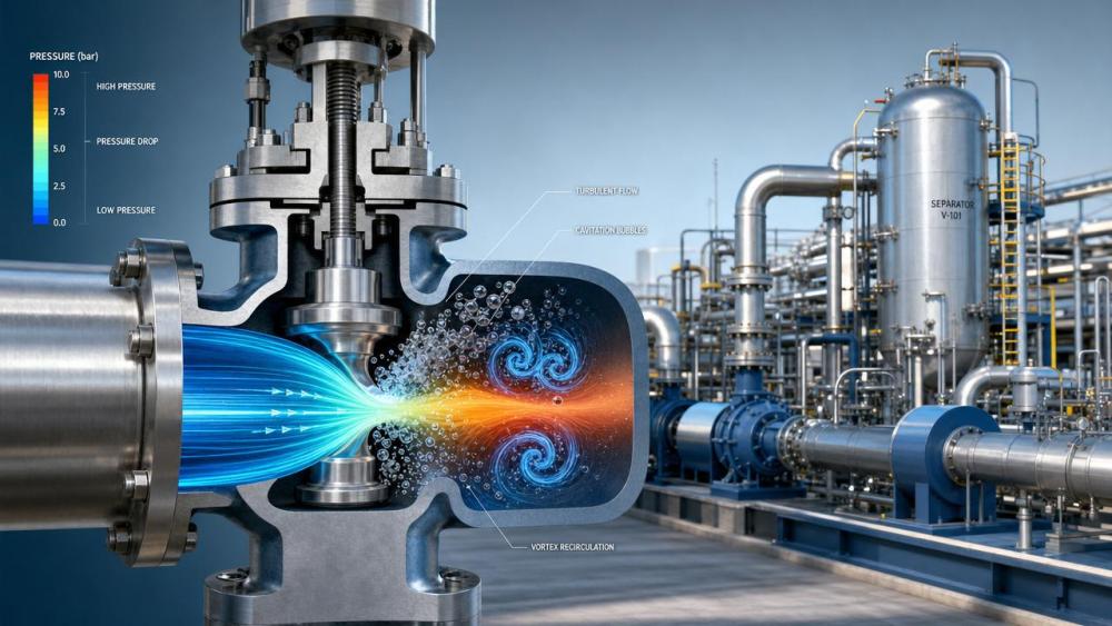
Pressure drop, jet impingement, recirculation zones, cavitation onset, and unstable velocity fields become visible and measurable.
In practical terms, CFD simulation analysis helps reduce design uncertainty and supports faster, more reliable valve selection.
For organizations tracking fluid control performance, this matters across pumps, compressors, separators, and automated piping networks.
At FCSM, this kind of insight sits at the center of smarter fluid control and lower lifecycle risk.
The value is straightforward: better visibility upstream leads to fewer surprises downstream.
Why valve flow problems are harder than they look
Valve flow issues often begin with a small mismatch between process demand and internal trim behavior.
A valve may pass acceptance tests, then struggle in real service because operating windows keep moving.
This is common in corrosive fluids, flashing liquids, mixed-phase streams, and high differential pressure conditions.
Traditional calculations still matter, but they cannot always show localized turbulence or hidden low-pressure pockets.
That gap is exactly where CFD simulation analysis becomes useful.
It helps answer questions that affect specification quality and commercial risk.
- Will the selected trim create excessive velocity at partial opening?
- Is cavitation likely during upset conditions, not only during nominal operation?
- Will the outlet flow pattern disturb downstream instrumentation or bends?
- Could pressure recovery trigger noise, vibration, or erosion over time?
When these questions are answered early, flow control decisions become much easier to defend.
What CFD simulation analysis reveals inside a valve
A strong CFD simulation analysis does more than produce colorful flow images.
It converts internal flow behavior into decision-ready evidence tied to valve performance and reliability.
The most valuable outputs usually include the following.
Pressure distribution
This shows where pressure falls too fast and where recovery may trigger cavitation or flashing.
It also helps compare actual behavior against expected pressure drop curves.
Velocity distribution
High local velocity often signals erosion risk, unstable throttling, or downstream disturbance.
CFD simulation analysis highlights where jets accelerate, split, or strike internal surfaces.
Turbulence intensity
Turbulence affects control stability, energy loss, and acoustic behavior.
In many cases, it explains why a valve performs well on paper but poorly in operation.
Cavitation indicators
For liquid service, cavitation risk is often the make-or-break issue.
A detailed CFD simulation analysis helps locate bubble formation zones and likely collapse regions.
Where simulation adds the most value in evaluation work
From recent project patterns, the strongest value appears when decisions involve uncertainty, cost exposure, or operational sensitivity.
That includes greenfield design, retrofit selection, recurring failure review, and performance guarantee checks.
In actual industrial settings, CFD simulation analysis is especially useful in these cases.
- Severe service valves with high pressure drop and tight control demands.
- Retrofits where line conditions changed but valve geometry stayed the same.
- Applications with frequent noise, vibration, or trim wear complaints.
- Projects requiring stronger technical justification for procurement approval.
- Critical units where shutdown costs make trial-and-error too expensive.
This also aligns with broader process industry trends.
More plants now expect digital validation before fabrication, not after field problems appear.
That shift makes CFD simulation analysis part of operational risk control, not just engineering optimization.
A practical workflow for valve CFD simulation analysis
A useful study starts with the right inputs, not with the software model.
When input quality is weak, even a polished simulation can mislead decisions.
A grounded workflow usually follows five steps.
1. Define operating envelopes
Use minimum, normal, maximum, and upset conditions.
Do not rely on a single design point.
2. Build realistic geometry
Include trim details, flow direction, nearby reducers, and sensitive downstream sections where relevant.
3. Select proper physical models
This may include turbulence models, cavitation models, compressibility effects, or multiphase assumptions.
4. Compare multiple openings
Partial opening often creates the highest risk, especially in throttling service.
5. Translate results into actions
The point is not to admire contours.
The point is to decide whether to change trim, material, size, staging, or operating strategy.
How to read CFD results without overestimating certainty
CFD simulation analysis is powerful, but it is not magic.
The real advantage comes from reading results with engineering discipline.
A few review habits make a big difference.
- Check whether boundary conditions reflect actual plant operation.
- Ask if the mesh is refined near trim edges and separation zones.
- Compare results with valve coefficients, lab data, or field observations.
- Focus on patterns and risk zones, not only on single numeric outputs.
- Review several cases instead of trusting one attractive simulation image.
This matters even more when procurement and reliability teams use the same results for final decisions.
A balanced CFD simulation analysis should reduce ambiguity, not hide it behind technical graphics.
Common valve problems that simulation can solve earlier
One of the clearest signals in modern projects is the cost of discovering flow problems too late.
Simulation helps move discovery to the design stage, where changes are cheaper and faster.
This is where CFD simulation analysis directly supports both reliability and capital efficiency.
Why this matters for modern fluid control strategy
Valve performance no longer sits in isolation.
It affects pump loading, compressor efficiency, separation quality, energy consumption, and maintenance planning.
That system-level view is increasingly important as plants pursue digitalization and decarbonization together.
FCSM tracks this shift closely across industrial centrifugal pumps, smart pneumatic control valves, compressor systems, and separation equipment.
In that context, CFD simulation analysis becomes a bridge between component behavior and strategic performance outcomes.
It helps teams verify whether a valve decision supports energy efficiency, stable throughput, and lower lifecycle emissions.
That is a stronger position than reacting after vibration, leakage, or wear already affects production.
Turning CFD simulation analysis into better decisions
The most effective use of CFD simulation analysis is simple.
Use it early, scope it around real operating envelopes, and link every result to a decision.
That decision may involve trim selection, valve sizing, cavitation control, material choice, or downstream layout.
The key is to move from visual insight to practical action without overstating certainty.
When done well, CFD simulation analysis shortens evaluation cycles and improves confidence in fluid control investments.
It also creates a stronger technical basis for discussions between engineering, operations, and commercial teams.
For valve flow problems, that kind of clarity is often the difference between repeated correction and first-time-right performance.
Start with the highest-risk valve case, validate the assumptions, and let CFD simulation analysis guide the next best move.
Related News
 How fluid control digitalization improves valve maintenance planningProcess Control ArchitectFluid control digitalization helps teams prioritize valve maintenance, reduce unplanned downtime, and improve reliability with actionable condition data.
 How smart valve positioners improve process control valve accuracyProcess Control ArchitectDiscover how smart positioners improve process control valve accuracy, reduce friction-related errors, enhance stability, and enable predictive maintenance.
 How to evaluate a valve automation supplier before placing an orderProcess Control ArchitectChoose a valve automation supplier with confidence. Learn how to assess engineering capability, compatibility, testing, lead times, and lifecycle support before ordering.
 How Does Industrial Automation Change Valve Specification Requirements?Process Control ArchitectHow does industrial automation change valve specification needs? Discover smarter sizing, diagnostics, protocols, fail-safe design, and lifecycle strategies for reliable control.
 Retrofit vs replacement automation: which option minimizes downtime?Process Control ArchitectRetrofit vs replacement automation: compare downtime, integration risk, lifecycle costs, and phased execution to protect uptime and modernize with confidence.
 When smart pneumatic control valves improve water treatment stabilityProcess Control ArchitectSmart pneumatic control valves for water treatment improve flow precision, dosing consistency, diagnostics, and plant stability. Learn how to select the right solution.
 When predictive maintenance for process valves pays off in plant operationsProcess Control ArchitectPredictive maintenance for process valves can cut downtime, reduce energy loss, and boost reliability. Learn when it pays off in plant operations—and how to justify the investment.
 Revised EN 14382:2026 Adds EMC Immunity Test for Smart Valve Positioners in EU ExportsProcess Control ArchitectEN 14382:2026 now mandates EMC immunity testing for Smart Valve Positioners, reshaping EU export compliance for valve OEMs and integrators. Learn what changed and how to prepare.
 FDA Tightens Import Rules for Smart Valve PositionersProcess Control ArchitectSmart valve positioners now face stricter FDA import rules. Learn how IEC 61508 SIL2 or UL 61508 documentation affects U.S. clearance, suppliers, and compliance planning.
 EN 14382:2026 Raises EU Entry Bar for Smart PositionersProcess Control ArchitectEN 14382:2026 raises the EU entry bar for Smart Valve Positioners with a 150 ms step response cap and IEC 62443-4-2 cybersecurity checks. Learn what exporters, buyers, and compliance teams must do before Nov 1, 2026.
 High-Precision Stainless Steel Control Valves for Corrosive Process LinesProcess Control ArchitectHigh-precision control valves stainless steel solutions improve corrosion resistance, flow stability, and safety in demanding process lines. Discover how to reduce downtime and boost control accuracy.
 How a Valve Performance Consultant Improves Uptime and Control AccuracyProcess Control ArchitectValve performance consultant insights to improve uptime, control accuracy, and energy efficiency. Learn how targeted diagnostics solve hidden valve issues across process systems.